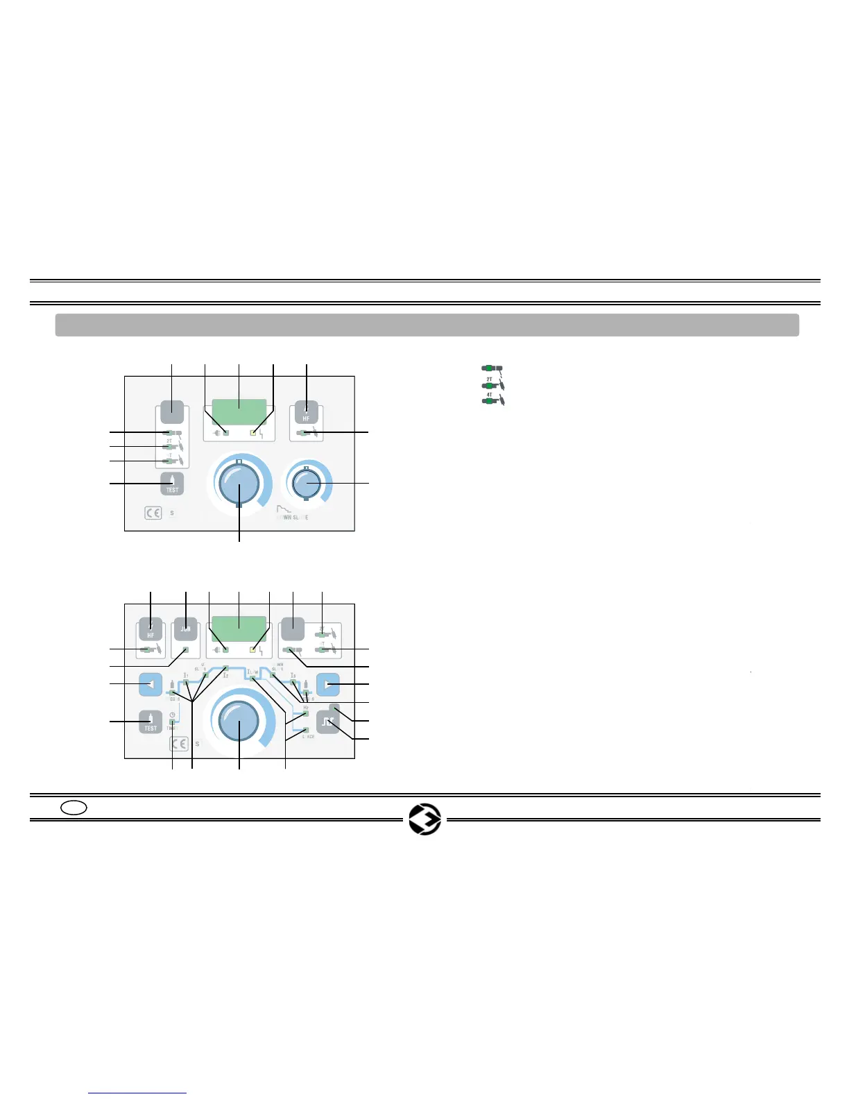
POS. 1 = Selection pushbutton for:
POS. 1A = ELECTRODE mode_____________________
POS. 1B = TIG 2 Times __________________________
POS. 1C = TIG 4 Times __________________________
POS. 2 = Power ON green LED
POS. 3 = Display showing SET and REAL welding current,
down slope ramp time
(on HFP series it also indicates the selected parameter)
POS. 4 = Alarm yellow LED ___________________________
POS. 5 = HF ON / OFF pushbutton ____________________
POS. 5A = HF ON / OFF led
POS. 6 = Down slope potentiometer _____________________
POS. 7 = Potentiometer for welding current regulation
(on HFP series it also indicates the selected parameter)
POS. 8 = TEST GAS pushbutton ____________________
POS. 9 = JOB selection and saving pushbutton __________
POS. 9A = JOB mode selected LED
POS. 10 = 11 and 14 parameters selection pushbutton
POS. 11 = LED mode selected:
(A) PRE GAS time __________________________
(B) INITIAL CURRENT
I1 _____________________
(C) UP SLOPE _____________________________
(D) WELDING CURRENT I2
(E) DOWN SLOPE __________________________
(F) FINAL CURRENT I3 ______________________
(G) POST GAS TIME _______________________
POS. 12 = PULSER selection pushbutton _________________
POS. 12A = PULSER ON / OFF LED
POS. 13 = Selected PULSER parameters LED
POS. 14 = TIMER selected modality LED _________________
Instruction Manual INOXA SERIES
4
GB
6. COMMANDS DESCRIPTION INOXA 250 HF / INOXA 360 HF / INOXA 250 HFP / INOXA 360 HFP
Fig. 1
1
2345
7
Page 7
Page 10
Page 10
Page 18
Page 11
Page 13
Page 8-16
Page 15
Page 14
Page 14
Page 13
Page 13
Page 14
Page 14
Page 14
Page 13
5
234
14
7
5A
6
1A
1B
1C
8
9
1 1B
1C
1A
10
5A
10
9A
12A
8
13
11
11
HF series
HFP series
12
A
B
C
D
E
F
G
H
I
L