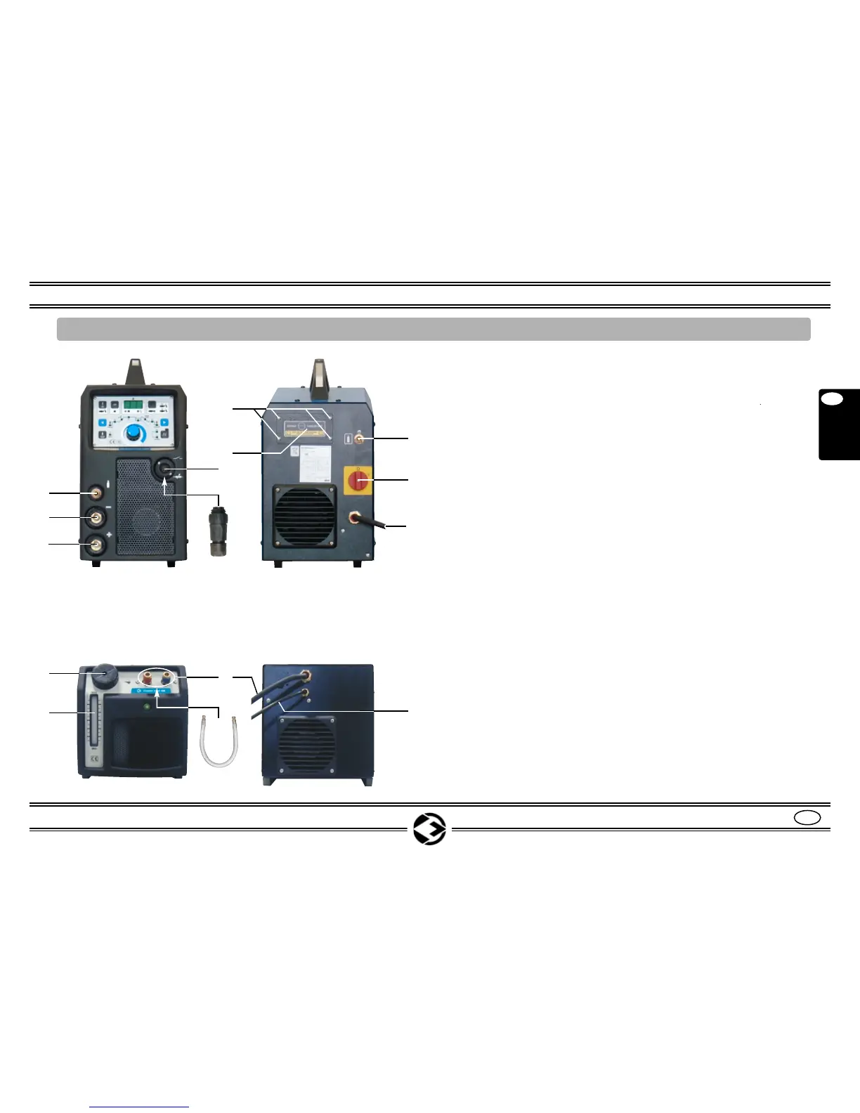
POS. 15 = 7-poles socket for remote control connection
TORCH SWITCH and REMOTE CONTROL _
POS. 15A = 7-poles plug for TORCH SWITCH ______________
(Connect the wires of the button of the torch to the
pins 1 and 4)
POS. 16 = Positive output Socket (+)
POS. 17 = Negative output Socket (-)
POS. 18 = GAS outlet for TIG welding ____________________
POS. 19 = GAS inlet for TIG welding _____________________
POS. 20 = Power source main switch “ON - OFF”
POS. 21 = Power input cable __________________________
POS. 22 = Door for the COOLER UNIT connection
POS. 22A = Screws for door fixing (22) ___________________
POS. 23 = Quick release connectors for inlet (blue) and
outlet (red)
POS. 23A = By-Pass tube with fast pluges
Connect to the fittings (23) if not used
POS. 24 = Coolig water level indicator
POS. 25 = Water tank cap
POS. 26 = Cable for flowmeter water signal ________________
POS. 27 = Cable for the power supply of the
COOLER UNIT _____________________________
5
Instruction Manual INOXA SERIES
GB
English
GB
6. COMMANDS DESCRIPTION INOXA 250 HF / INOXA 360 HF / INOXA 250 HFP / INOXA 360 HFP
Fig. 2
15
17
16
20
21
18
22
22A
19
15A
Page 7-8-17
Page 8
Page 8
Page 8
Page 3
Page 9
Page 9
Page 9
Page 9
25
24
23
23A
27
26
Cooler Unit 09 (Optional)