4.
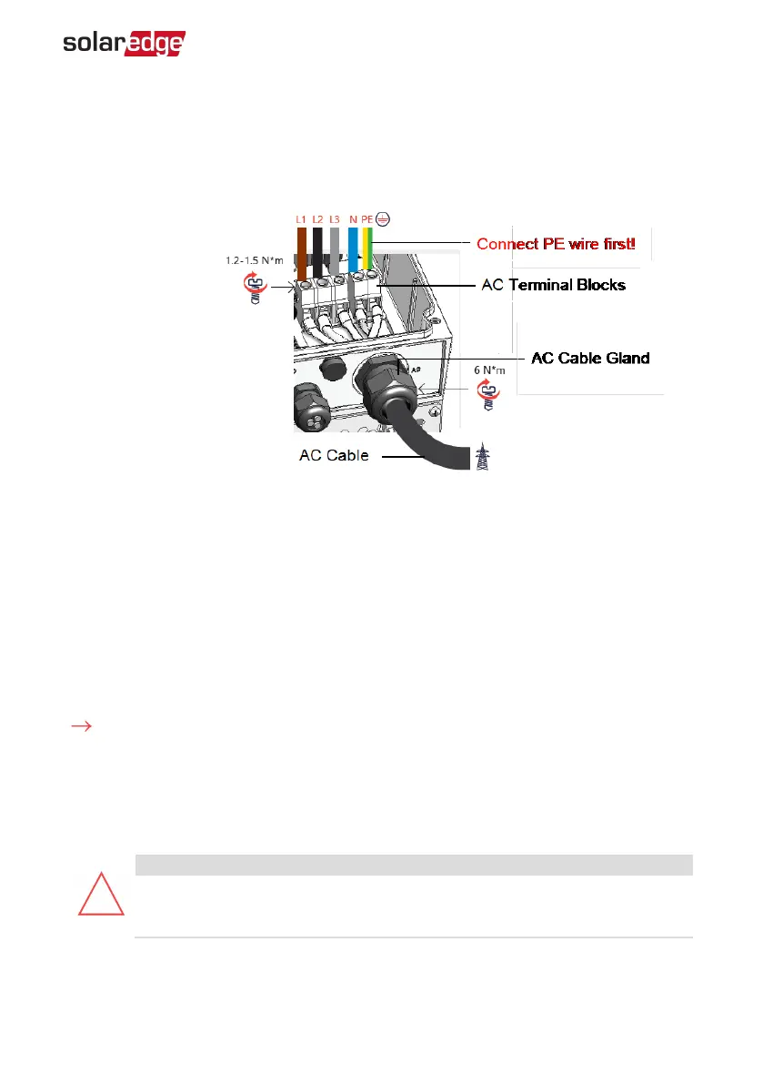
Open the AC cable gland and insert the AC Cable through the gland
.
5.
Connect the wires according to the labels on the AC Terminal Blocks inside the
inverter - connect the PE wire first. Tighten the screws of the terminal block with a
torque of 1.2-1.5 N*m / 0.88-1.1 lb*ft.
Figure 16: Connection of AC Cable to the Inverter
6. Tighten the AC Cable Gland with a torque of 6 N*m / 4.4 lb*ft.
7. Verify that all wires are firmly tightene
d to the terminal blocks. Check that the wires
are fully inserted and cannot be pulled out easily. Ensure that unused terminal block
screws are tightened.
8. Close the inverter cover and tighten the screws with a torque of 9 N*m / 6.6 lb*ft.
Connecting the ACGrid to the DC Safety Unit
To connect the AC grid to the DC Safety Unit:
1. Turn OFF the AC circuit breaker.
2. Release thesix Allen screws and carefully remove the inverter cover by pulling out
the cover and lowering it down.
3. Release the four Allen screws and remove the cover of the DC Safety Unit.
CAUTION!
When removing the cover, make sure not to damage internal components.
SolarEdge will not be held responsible for any components damaged as a
result of incautious cover removal.
Chapter 4: Connecting AC and PVStrings to the Inverter 34
Three Phase Inverter with SetApp Configuration PN: SEXXK-XXXXIXXXX