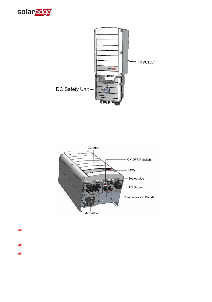
Figure 4: Inverter with DC Safety Unit
Inverter Interfaces
Figure 5
shows the inverter connectors and components, located at the bottom of the
inverter.
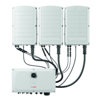
Figure 5: Inverter Interfaces
ACoutput: ACoutput gland, AC cable external gauge, 19-28mm diameter for
connection to the grid
DC input: MC4 connector, for connection of the PV installation.
Two communication glands: for connection of inverter communication options.
Each gland has three openings. Refer to
Setting Up Communication with the
Monitoring Platform
on page 46 for more information.
Chapter 3: Installing the Inverter 22
Three Phase Inverter with SetApp Configuration PN: SEXXK-XXXXIXXXX