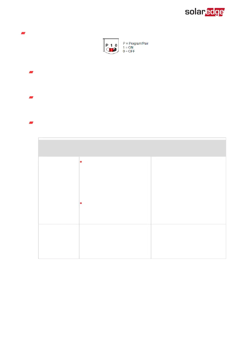
P/ON/OFF switch:
Figure 6: ON/OFF/P switch
ON (1) - Turning this switch ON (after power optimizer pairing) starts the
operation of the power optimizers, enables power production and allows the
inverter to begin exporting power to the utility grid.
OFF (0) - Turning this switch OFF reduces the power optimizer Voltage to a low
safety Voltage and inhibits exportation of power. When this switch is OFF, the
control circuitry remains powered up.
P - Moving and releasing the switch allows viewing system information via the
LEDs, and performing the following functions:
P Position
Duration
Function Comments
Switch moved
to P for 2
seconds, then
released.
Displays (via
LEDs)production
information for 5 seconds,
or error type indications (if
exist) for 5 seconds.
Activates the Wi-Fi access
point for connecting to the
SetApp
While the switch is in P, all
LEDs are ON.
When the switch is released all
LEDs turn OFF for 0.5 sec and
then display the production or
error indication.
Switch moved
to P for more
than 5 seconds,
then released.
Starts pairing
Pairing is indicated by all 3
LEDs blinking simultaneously.
LEDs
Three Phase Inverter with SetApp Configuration PN: SEXXK-XXXXIXXXX
23 Inverter and DC Safety Unit Interfaces