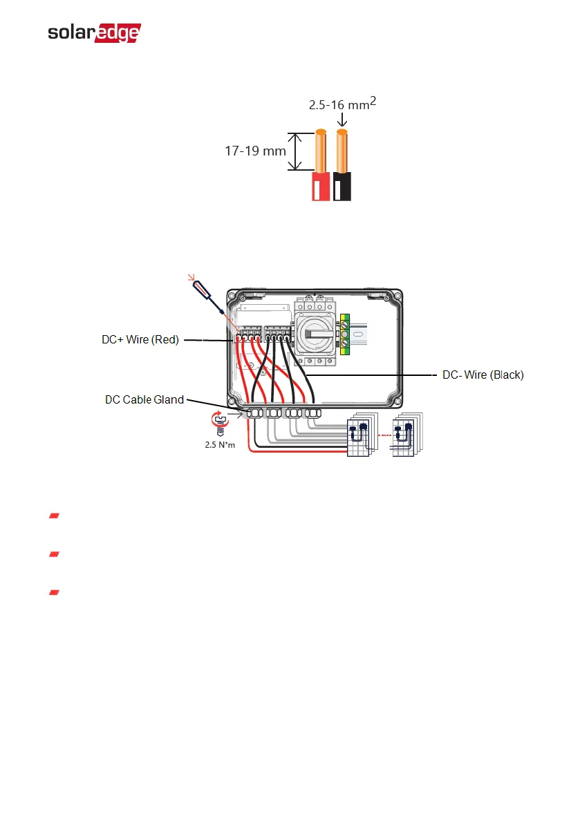
5.
Strip 17-19 mm of the DC wire insulation.
6.
Insert the wires into the DC input glands of the DC Safety Unit.
7.
Connect the DC wires according to the DC+ and DC- labels on the terminal blocks.
Use a screwdriver blade that fits freely into the release mechanism opening on the
terminal block. Too large a blade can crack the plastic housing.
Insert the screwdriver into the terminal block and press the release mechanism and
open the clamp.
Insert the conductor of the wire into the round opening and remove the screwdriver
– the wire is automatically clamped.
8.
Verify that all wires are connected firmly.
9. Tighten the glands with a torque of 2.5 N*m.
10.
Close the DC Safety Unit cover and secure it by tightening the four screws with a
torque of 10.3 N*m / 7.6 ft.*lb.
11.
Ensure proper cable entry sealing: inspect the entire cable run and use standard
sealant to avoid water penetration.
Chapter 4: Connecting AC and PVStrings to the Inverter 38
Three Phase Inverter with SetApp Configuration PN: SEXXK-XXXXIXXXX