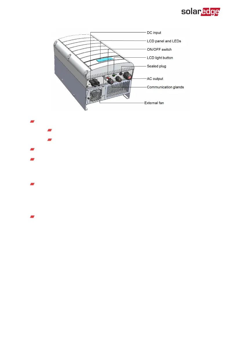
Figure 5: Inverter Interfaces
ACoutput: AC cable external gauge:
Single phase inverters: PG21 (9-16mmdiameter)
Three phase inverters: M32 (15-21mm diameter)
DC inputs: For connection of the PV installation
Two communication glands, for connection of inverter communication
options. Each gland has three openings. Refer to
Setting Up Communication
on
page 66 for more information.
LCD light button: Pressing this button lights up the LCD for 30 seconds. In
addition, you can press this button to view inverter status screens and access
configuration menu options, as described
Configuring the Inverter Using the
LCD Light Button
on page 48.
ON/OFF switch: Turning this switch ON (after the power optimizers are paired
with the inverter) starts the operation of the power optimizers, enables power
production and allows the inverter to begin exporting power to the utility grid.
Turning it OFF reduces the power optimizer voltage to a low safety voltage and
inhibits exportation of power. When this switch is OFF, the inverter control
circuitry remains powered up.
-Three Phase System Installation Guide MAN-01-00057-4.1
24 Inverter Interfaces