EasyManuals Logo

SolarEdge SE3000 User Manual

SolarEdge SE3000
114 pages
To Next Page IconTo Next Page
To Previous Page IconTo Previous Page
Page #70 background imageLoading...
Page #70 background image
Communication Connectors
Two communication glands are used for connection of the various communication
options. Each gland has three openings. The table below describes the functionality of
each opening. Unused openings should remain sealed.
Gland# Opening Functionality Cable size (diameter)
1 (PG16)
One small External antenna cable 2-4 mm
Two large
Ethernet connection
(CAT5/6), Cellular, ZigBee,
or Wi-Fi
4.5-7 mm
2 (PG13.5) All three RS485, power reduction 2.5-5 mm
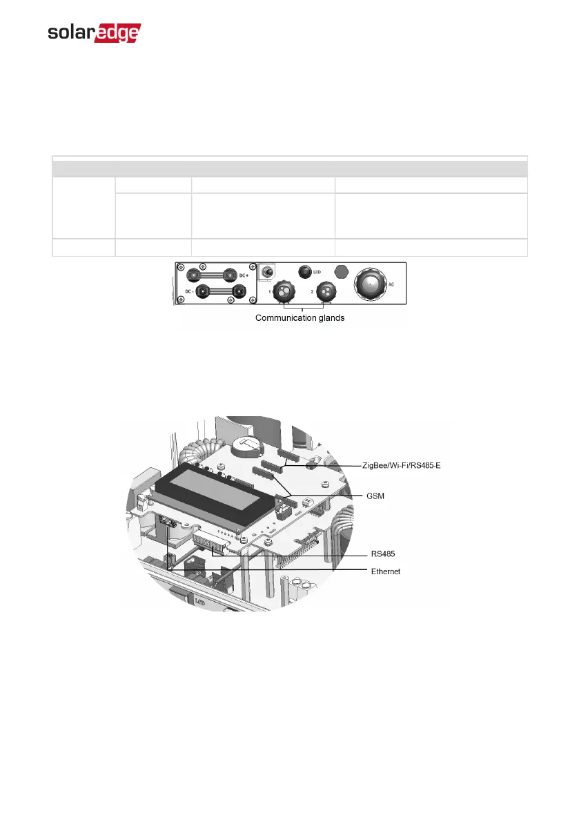
Figure 19: Communication Glands
The communication board has a standard RJ45 terminal block for Ethernet connection,
and a 9-pin terminal block for RS485 connection, as shown below:
Figure 20: Internal connectors
Chapter 7: Setting Up Communication 69
Three Phase System Installation Guide MAN-01-00057-4.1

Table of Contents

Questions and Answers:

Question and Answer IconNeed help?

Do you have a question about the SolarEdge SE3000 and is the answer not in the manual?

SolarEdge SE3000 Specifications

General IconGeneral
ModelSE3000
ManufacturerSolarEdge
AC Output Power3000 W
CoolingNatural Convection
Protection RatingIP65
Rated AC Power3000 W
Max. AC Power3000 VA
Maximum Output Current13 A
Number of MPP Trackers1
Operating Temperature Range-25°C to 60°C
AC Voltage230 V
Max. Input DC Voltage480 V

Related product manuals