Chapter 3: Installing the Inverter
Install the inverter either before or after the modules and power optimizers have been
installed.
CAUTION!
Do not rest the connectors at the bottom of the inverter on the ground, as it
may damage them. To rest the inverter on the ground, lay it on its back, front
or side.
Inverter Package Contents
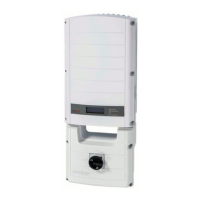
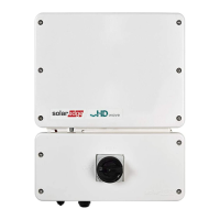
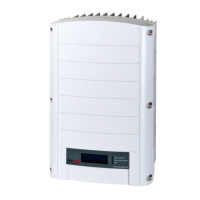
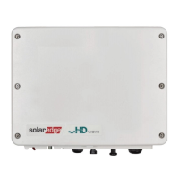
One inverter with DC Safety Unit
One mounting bracket
Two Allen screws for fastening the inverter to the mounting bracket
Installation guide (with activation card and instructions)
Optional (for wireless communication to monitoring platform) - RF antenna and
mounting bracket
AC ferrite bead kit
Identifying the Inverter
Refer to the sticker on the inverter that specifies its Serial Number and its Electrical
Ratings. Provide the serial number when contacting SolarEdge support. The serial
number is also required when opening a new site in the monitoring platform.
Inverter Interfaces
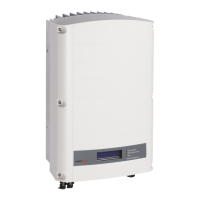
The following figure shows the inverter connectors and components, located at the
bottom of the inverter.
Chapter 3: Installing the Inverter 23
Three Phase System Installation Guide MAN-01-00057-4.1
 Loading...
