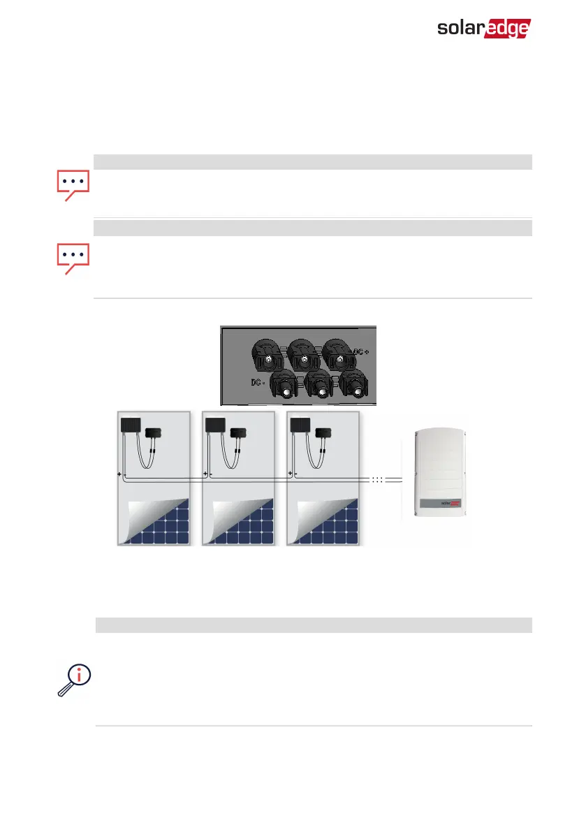
Connecting the Strings to the Inverter
Connect the string to the DC input pairs. If required, connect additional strings in
parallel using an external combiner box/branch cables before connecting to the
inverter.
NOTE
Functional electrical earthing of DC-side negative or positive poles is prohibited
because the inverter has no transformer. Grounding (earth ground) of module
frames and mounting equipment of the PV array modules is acceptable.
NOTE
SolarEdge’s fixed input voltage architecture enables the parallel strings to be of
different lengths. Therefore, they do not need to have the same number of
power optimizers, as long as the length of each string is within the permitted
range.
Connect the DC connectors of each string to the DC+ and DC- connectors .
Figure 15: Inverter DC Connections
Selecting a Residual Current Device (RCD)
IMPORTANTSAFETYFEATURE
All SolarEdge inverters incorporate a certified internal Residual Current Device
(RCD) in order to protect against possible electrocution and fire hazard in case
of a malfunction in the PV array, cables or inverter. There are 2 trip thresholds
for the RCD as required for certification (DIN VDE 0126-1-1). The default value
for electrocution protection is 30 mA, and for slow rising current is 300 mA.
-Three Phase System Installation Guide MAN-01-00057-4.1
34 Connecting the Strings to the Inverter