NOTE
If using a cable longer than 10 m / 33 ft in areas where there is
a risk of induced voltage surges by lightning, it is recommend
to use external surge protection devices.
For details refer to: http://www.solaredge.com/files/pdfs/lightning_
surge_protection.pdf.
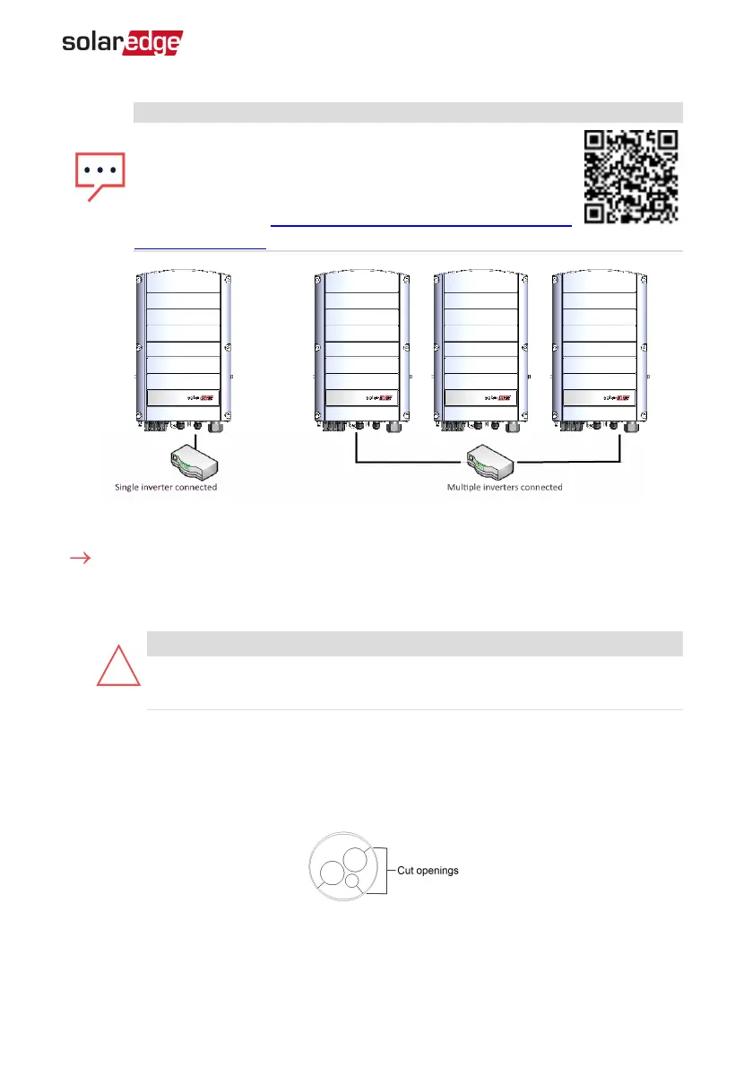
Figure 21: Example of Ethernet connection
To connect the Ethernet cable:
1. Remove the inverter cover .
2.
Open the communication gland #1.
CAUTION!
The gland includes a rubber waterproof fitting, which should be used to
ensure proper sealing.
3. Remove the plastic seal from one of the large opening .
4. Remove the rubber fitting from the gland and insert the CAT5/6 cable through the
gland and through the gland opening in the inverter .
5.
Push the cable into the cut opening of the rubber fitting.
Figure 22: Rubber fitting
Chapter 7: Setting Up Communication 71
Three Phase System Installation Guide MAN-01-00057-4.1