EasyManuals Logo

SolarEdge SE5000 User Manual

SolarEdge SE5000
114 pages
To Next Page IconTo Next Page
To Previous Page IconTo Previous Page
Page #77 background imageLoading...
Page #77 background image
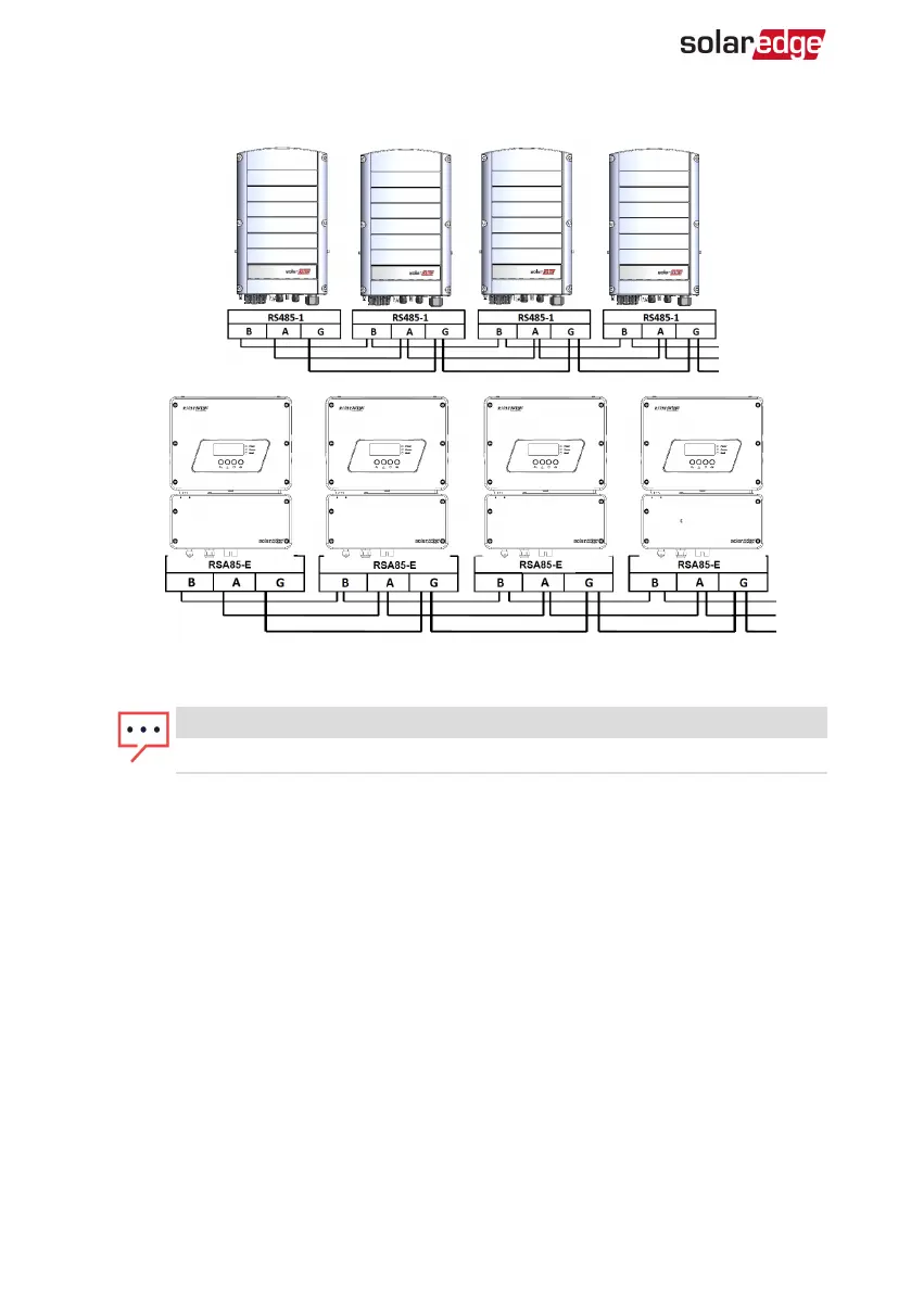
figure shows this connection schema:
Figure 27: Connecting the inverters in a chain
NOTE
Do not cross-connect B, A and G wires.
7. Tighten the terminal block screws.
8. Check that the wires are fully inserted and cannot be pulled out easily.
9.
Push the RS485 terminal block firmly all the way into the connector on the right side
of the communication board.
10.
Terminate the first and last SolarEdge device in the chain by switching a termination
DIP-switch inside the inverter to ON (move the left switch up). The switch is located
on the communication board and is marked SW7SW1.
-Three Phase System Installation Guide MAN-01-00057-4.1
76 Creating an RS485 Bus Connection

Table of Contents

Questions and Answers:

Question and Answer IconNeed help?

Do you have a question about the SolarEdge SE5000 and is the answer not in the manual?

SolarEdge SE5000 Specifications

General IconGeneral
ModelSE5000
ManufacturerSolarEdge
CategoryInverter
AC Output Power5000 W
Efficiency98.3%
CoolingNatural convection
Protection RatingIP65
Rated AC Power5000 W
Max. AC Power5000 VA
Maximum Input Voltage480 V
Number of MPP Trackers1
Max. Input DC Voltage480 V
Operating Temperature Range-25°C to 60°C
AC Voltage230 V

Related product manuals