42
Startup of the Inverter
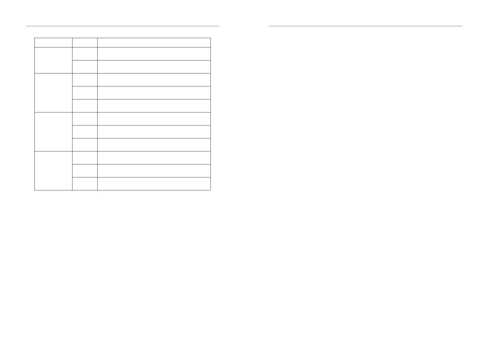
43
Communication signal
indicator
(blue)
DC side signal indicator
(green)
Grid connection indicator
(green)
Inverter fault indicator
(Red)
Always light on
Flashing
Always light on
Always light off
Flashing
Always light on
Always light off
Flashing
Always light on
Always light off
Flashing
The inverter communication is normal.
No communication data is sent or received for a long time.
The inverter is in grid-connected state.
If the fault signal light is on, it indicates errors occur on the inverter DC side. If the fault
signal light is off, it indicates no errors occur on the inverter DC side and at least one
channel of MPPT input voltage is higher than 200 V.
The input voltage of all channels of MPPT is less than 200 V; Or DC switch is not
turned on.
The inverter is in grid-connected state.
If the fault signal indicator is on, it indicates errors occur on inverter AC side; If the
fault signal indicator is off, AC grid is connected and the inverter is not in grid-
connected state.
The inverter is not connected to the grid;
The inverter prompts warning
The inverter is faulty
The inverter is currently in a normal state, and there is no fault.
LED Indicator status Indicator status definition
● Four LED lights have three states:
Always on / always off / flashing
The specific definitions are as follows:
Note:
When there is firmware in the inverter system in the upgrading state, the other 3 LED
lights are in the flashing state except the communication signal light; Do not operate
the inverter before upgrading finished.
Troubleshooting
8 Troubleshooting
8.1 Troubleshooting
This section contains information and procedures for solving possible problems with
X3 series inverters, and provides you with troubleshooting tips to identify and solve
most problems that could occur with the X3 series inverters.
This section will help you narrow down the source of any problems you may
encounter. Please read the following troubleshooting steps.
Check warnings or fault messages on System Control Panel or Fault codes on the
inverter information panel. If a message is displayed, record it before doing anything
further.
Attempt the solution indicated in troubleshooting lists.
Contact SolaX Customer Service for further assistance. Please be prepared to
describe details of your system installation and provide model and serial number
of the unit.
Global Service Center: +86 (571) 56260033 ext 749
General Enquiry: +86 (571) 56260011
Sales Enquiry: +86 (571) 56260008
E-Mail: info@solaxpower.com
Fax: +86 (571) 56075753
If your inverter's information panel is not displaying a Fault light, check the following list
to make sure that the present state of the installation allows proper operation of the
unit.
— Is the inverter located in a clean, dry, adequately ventilated place?
— Have the DC input breakers been opened?
— Are the cables adequately sized and short enough?
— Are the input and output connections and wiring in good condition?
— Are the configurations settings correct for your particular installation?
— Are the display panel and the communications cable properly
connected and undamaged?