10
11
Safety Introduction
2.4 EC Directives
This chapter follows the requirements of the European low voltage directives,
which contains the safety instructions and conditions of acceptability for the
endues system, which you must follow when installing, operating and servicing
the unit. If ignored, physical injury or death may follow, or damage may occur
to the unit. Read this instructions before you work on the unit. If you are unable
to understand the dangers, warnings, cautions or instructions, contact an
authorized service dealer before installing. Operating and servicing the unit.
The Grid connected inverter meets the requirement stipulated in Low Voltage
Directive (LVD) 2014/35/EU and Electromagnetic Compatibility (EMC)
Directive 2014/30/EU. The unit is based on:
EN 62109-1:2010; EN 62109-2:2011; IEC 62109-1 (ed.1) ; IEC62109-2
(ed.1); EN 61000-6-3:2007+A:2011; EN 61000-6-1:2007; EN 61000-6-
2:2005
In case of installation in PV system, startup of the unit (i.e. start of designated
operation) is prohibited until it is determined that the full system meets the
requirements stipulated in EC Directive (2014/35/EU, 2014/30/EU, etc.)
The grid connected inverter leave the factory completely connecting device
and ready for connection to the mains and PV supply, the unit shall be installed
in accordance with national wiring regulations. Compliance with safety
regulations depends upon installing and configuring system correctly,
including using the specified wires. The system must be installed only by
professional installers who are familiar with requirements for safety and EMC.
The installer is responsible for ensuring that the end system complies with all
the relevant laws in the country where it is to be used.
The individual subassembly of the system shall be interconnected by means of
the wiring methods outlined in nationa / international such as the national
electric code (NFPA) No.70 or VDE regulation 0107.
A B
C
A
D
C
E
E
Warning!
• The inverter shall not be connected to the PV string
requiring positive grounding or negative grounding.
Do not connect local load between inverter and AC
side circuit breaker!
The power grid supported by X3-Forth inverter are TN-S, TN-C, TN-C-S,
TT and IT.
40 kW-70 kW inverters are connected to 220 V / 127 V three-phase four
wire power grid and 80 kW-120 kW inverters are connected to 380V /
400V three-phase four wire power grid, which must be connected with N
line (or not), as shown in Figure 1;
136 kW and 150 kW models are directly connected to the medium
voltage power grid through 500 V or 540 V transformer without N line
access, as shown in Figure 2;
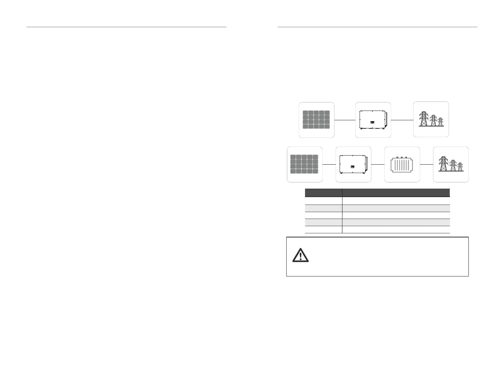
3. Introduction
3.1 Photovoltaic grid connected system
X3-Forth, a three-phase transformerless grid connected inverter, is an important
part of photovoltaic power generation system. It converts the direct current
generated by the photovoltaic panel into alternating current and also can be
used to optimize self-consumption or feed into the public grid. The first figure shows
the typical application scenario of 40k-125k inverter and the second
figure shows the typical application scenario of 136k-150k inverter.
Object
A Photovoltaic string
B
C
D
Description
X3-Forth 136K-150K inverter
X3-Forth 40k-125k inverter
Power grid
NO.
E
Transformer
Defination