1.1 Scope of Validity
This manual is an integral part of X3-Forth Series, It describes the assembly,
installation, commissioning, maintenance and failure of the product. Read it
carefully before operating.
Note: “X3”: means three phases, “FTH” means Forth, “80K” means 80 kW. Each
model is available with LED indicator lights and LCD.
40K/50K/60K/70K inverters works in the 220 V / 127 V low voltage range.
80K/100K/110K/120K/125K inverters works in the 220 V / 380 V voltage
range.
136K/150K inverters works in the 500 V / 540 V medium voltage range.
Keep this manual at the place where it is accessible all the time.
1.2 Target Group
This manual is for qualified electricians. The tasks described in this manual only
can be performed by qualified electricians.
1.3 Symbols Used
The following types of safety instructions and general information appear in this
document as described below:
1 Notes on this Manual
Notes on this Manual
03
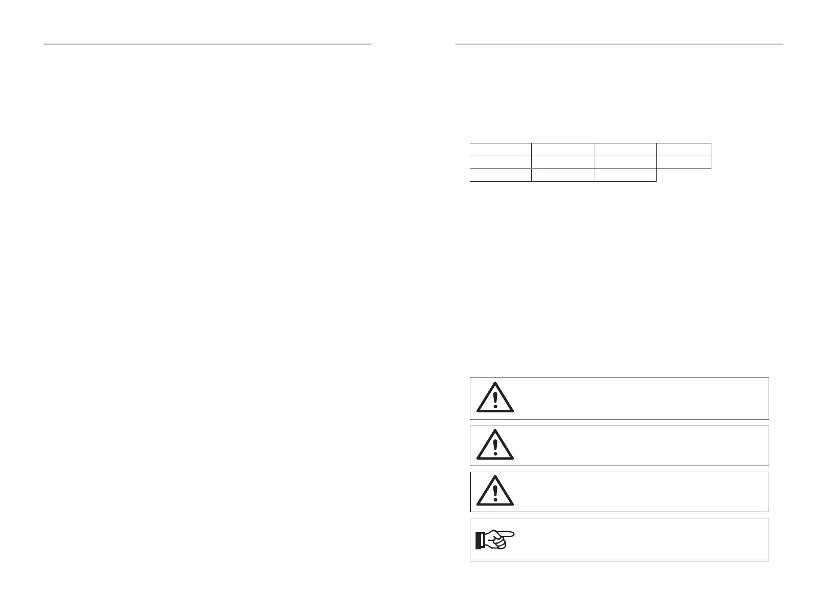
DANGER!
“Danger” indicates a hazardous situation which, if not avoided, will
result in death or serious injury.
WARNING!
“Warning” indicates a hazardous situation which, if not avoided,
could result in death or serious injury.
CAUTION!
“Caution” indicates a hazardous situation which, if not avoided,
could result in minor or moderate injury.
NOTE!
“Note” provides tips that are valuable for the optimal operation of
your product.
5.6 INSTALLATION STEPS......................................................................................
5.6.1 INSTALLATION STEPS (ON THE WALL) .....................................
5.6.2 INSTALLATION STEPS (ON THE STAND)...................................
6 ELECTRICAL CONNECTION.............................................................................
6.1 GROUNDING CONNECTION......................................................................
6.2 PV STRING CONNECTION............................................................................
6.3 GRID CONNECTION......................................................................................
6.4 COMMUNICATION CONNECTION..........................................................
6.4.1 COMMUNICATION SIGNAL DEFINITION.................................
6.4.2 CONNECTION STEPS OF CABLE...............................................
6.4.3 RELEASE STEPS OF CABLE...........................................................
6.5 MONITORING CONNECTION.....................................................................
7 STARTUP OF THE INVERTER............................................................................
8 TROUBLESHOOTING..........................................................................................
8.1 TROUBLESHOOTING.....................................................................................
8.2 ROUTINE MAINTENANCE............................................................................
9 DECOMMISSIONING...........................................................................................
9.1 DISMANTLING THE INVERTER.....................................................................
9.2 PACKAGING........................................................................................................
9.3 STORAGE AND TRANSPORTATION...........................................................
9.4 DISPOSING OF THE X3-FORTH....................................................................
10 DISCLAIMER ..........................................................................................................
* WARRANTY REGISTRATION FORM
Contents
02
26
26
27
29
29
30
33
36
36
37
38
39
41
43
43
48
50
50
50
50
50
51
X3-FTH-60K-LV
X3-FTH-50K-LV
X3-FTH-40K-LV
X3-FTH-136K-MV
X3-FTH-150K-MV
X3-FTH-70K-LV
X3-FTH-110K
X3-FTH-100K
X3-FTH-80K
X3-FTH-125K
X3-FTH-120K