Electrical Connection
Bracket
M10x40 bolt
combination
b) Use the bracket as a template for marking the position of drilling holes on
the stand with a digital level and marker.
c) Use φ10 drill to drill holes in accordance with the mark. The depth of the
holes shall be at least 35 mm.
d) Pre-install the bracket on the stand and screw in the M10X40 screws.
b) c) d)
Ø Step 2: Hang the inverter on the bracket
a) Lift up the inverter. Two methods are available for your choice.
Method 1: Four installers directly hold the inverter on the two sides and lift
it up.
Method 2: Install two lifting rings on the two sides of inverter and lift it up.
a)
b) Hang the inverter on the bracket and secure it on the bracket with M8
bolts.
b)
The uncharged metal parts in the photovoltaic power generation system,
including the photovoltaic substrate bracket and the metal shell of the
inverter, should be reliably grounded. The grounding part of multiple
inverters and photovoltaic array shall be connected to the same grounding
bus to establish reliable equipotential connection.
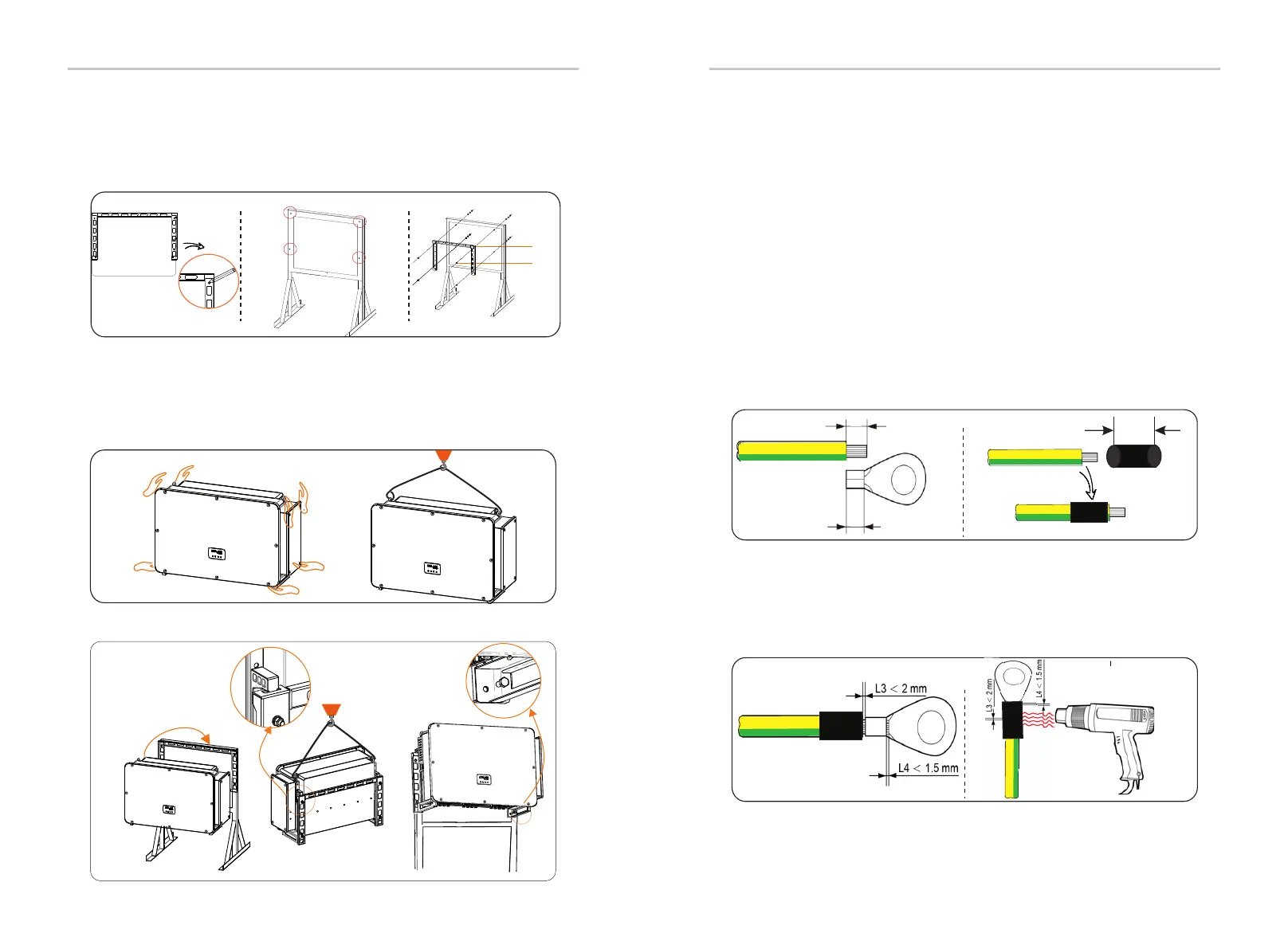
a) Select 35-70 mm² yellow and green conductor with proper length
by wire cutter and OT copper terminal. Use wire stripper to strip the
insulation layer of the conductor end. The stripped length shall be as
shown below:
b) Tighten the stripped end and pull the heat-shrink tubing over the
grounding cable. The heat-shrink tubing must be at below cable section.
6. Electrical connection
Ø Step 1: Make the grounding cable
A=B+(2~3mm)
B
C=A+2cm
Heat-shrink tubing
a) b)
6.1 Groundng connection
Mechanical Installation
28
29
c) Insert the stripped section into the OT copper terminal and crimp
with crimping tool.
d) Pull the heat-shrink tubing over the stripped section of OT terminal
and use hot-air blower to shrink it so that it can be in firm contact with OT
terminal.
c) d)