Electrical Connection
Electrical Connection
36 37
6.4 Communication Connection
6.4.1 Communication signal definition
Inverter RS485
networking or connect
the data collector
Port
Pin
Definition
Remark
RS-485-1
RS-485-2
DRM
1
2
3
4
5
6
7
8
9
10
11
12
13
14
15
16
RS485A IN+
RS485B IN-
Rs485 IN-GND
RS485A OUT+
RS485B OUT-
RS485A METER
RS485B METER
V+5V
COM_GND
DRM1/5
DRM2/6
DRM3/7
DRM4/8
RG/0
CL/0
Rs485OUT-GND
ConnecttheRS485meter
orotherdevices
Reserved for DRM
DI
21
22
Digital IN+
Digital IN-
Inputdigitalsignal
DO
29
30
Digital OUT+
Digital OUT-
Outputdigitalsignal
1
11
21
10
20
30
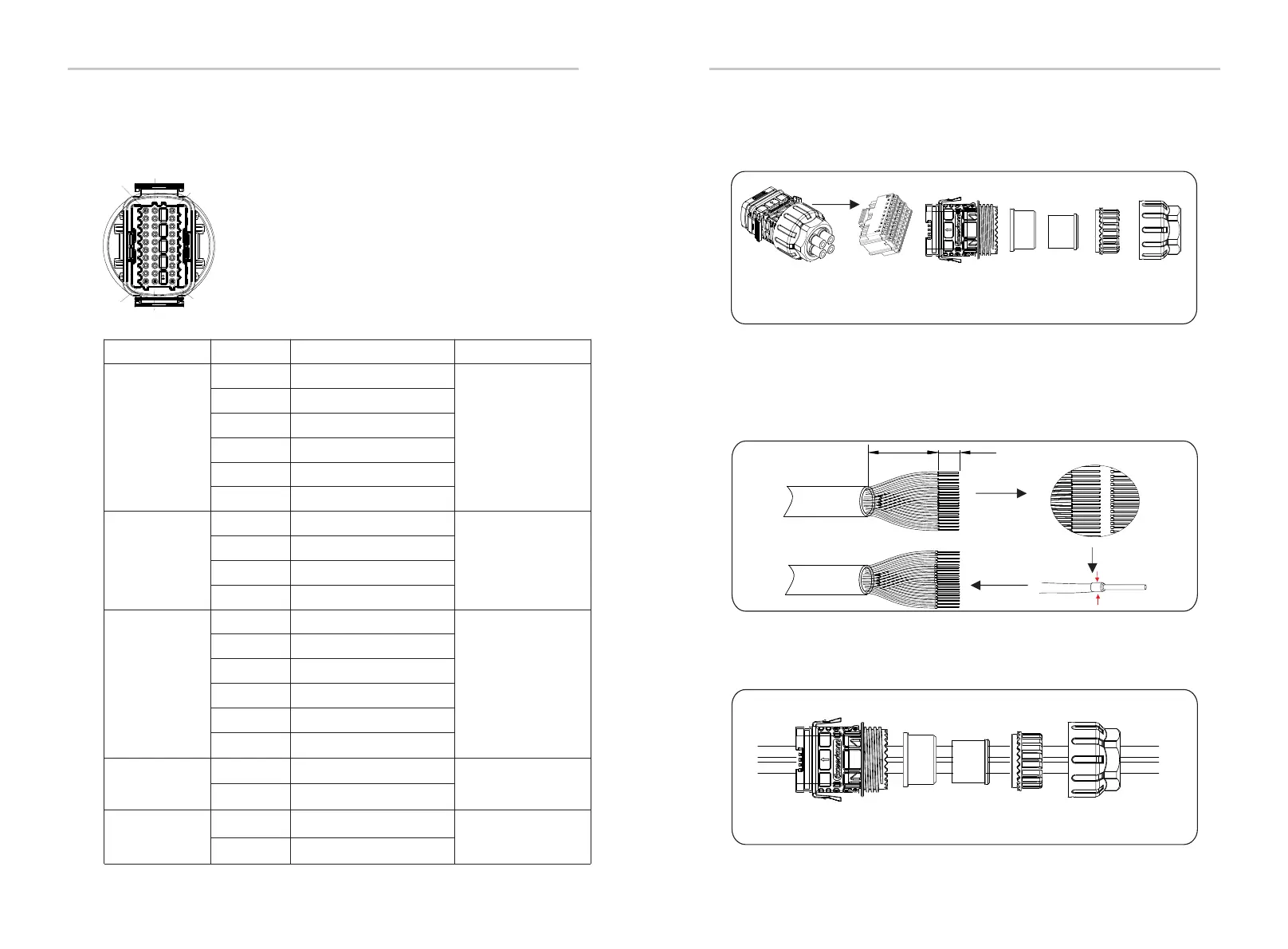
6.4.2 Connection steps of communication cable
a) Find out the communication terminal from the accessory bag and
disassemble it into the following parts.
b) Select 0.5-0.75 mm2 conductor and use wire stripper to strip 12-14
mm insulation layer of the cable end and insert the insulated cord end terminal
to the cable end. (ENY0512 nylon terminal for 0.5mm²/22 AWG conductor;
ENY7515 nylon terminal for 0.75mm²/20 AWG conductor)
c) Use terminals press clamp to make the terminal in firm contact with the
cable end.
20-2 5 mm
12-1 4 mm
COM terminal Housing Body Seal ring Seal body Claw nut
d) Set the nut, claw, seal body, seal ring and body on the communication
cable in turn.
V
PV connection
Body, Seal ring, Seal body, Claw, nut