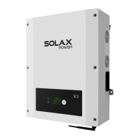
10. Separate the DC connector
a. Use the specified wrench tool.
b. When separate the DC+ connector, push the tool down from up side.
c. When separate the DC- connector, push the tool down from the bottom
side.
d. Separate the connectors by hands.
Before connecting, disconnecting the connection between solar
generator and inverter and locked it to the open position during
installation. Place a warning sign“do not turn on maintenance in
progress” on the external disconnect switch when it is shut Down,
and make sure that on-off remote controls are inhibited.
WARNING!
AC Output
Must comply with the connection requirement of your distribution
grid.
WARNING!
ZDNY series inverters are designed for three phase grid. Voltage range is
from 230V +20%,according to different countries. The typical frequency is
50Hz. Other technical requests should comply with the requirement of
local public grid. For the terminal and cable design please follow below
requirements.
Terminal capacity and Identification.
Connection
type
Rated connecting
capacity and rating
Stripping
length
Tightening
torque
Torx-head
Screw(m5)
Amphenol(MC4)
Amphenol
Connector
1.8-2Nm
1.8-2Nm
1.8-2Nm
-----------
Protective earthing
connection
DC input connection
ACoutput connection
RS485
-----------
-----------
11mm
-----------
-----------
-----------
25A 1000V
25A 380V
Connection
type
Rated connecting
capacity and ratings
Tighting
torque
Stripping
length
Earth conductor: PE screw terminal designed for clamping a cable lug or bar by means
of a screw, nut and locking washer, before PE connection, strip the conductor end 12mm
long to fit them into a cable lug or bar. For PE connection, the length of conductors
between the cord anchorage and the terminal,shall be such that the current-carrying
conductors became taut before the earthing conductor if the cable slips out of the cord
anchorage.
ZDNY-TL
10000
ZDNY-TL
12000
ZDNY-TL
15000
ZDNY-TL
10000
ZDNY-TL
20000
Cable(Cu) (mm²)
Micro-breaker(A)
≥6
2525323232
●Connection Step:
1. Check the grid voltage and compare with the permissible voltage range.
(see technical data).
2. Disconnect the circuit-breaker from all the phases and secure against
re-connection.
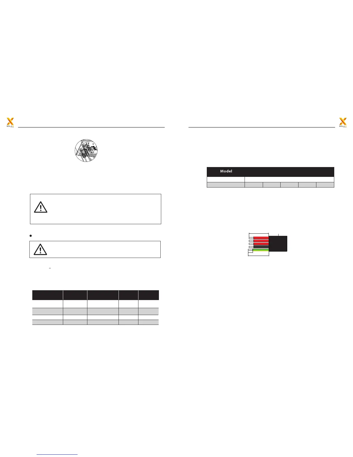
3. Trip the wires:
a. Trip all the wires to 52.5mm and the PE wire to 55mm.
b. Use the crimping pliers to trip 12mm of insulation from all wire ends as
below.
4.Separate the AC plug into three parts as below.
a: Hold the middle part of the female insert,rotate the back shell to loosen it,
and datach it from female insert.
b:Remove the cable nut(with rubber insert) from the back shell.
5:Slide the cable nut and then back shell onto the cable.
52.5mm
12mm
55mm
Outer jacket
S
N
PE
T
R
23
22
5 Installation5 Installation
 Loading...