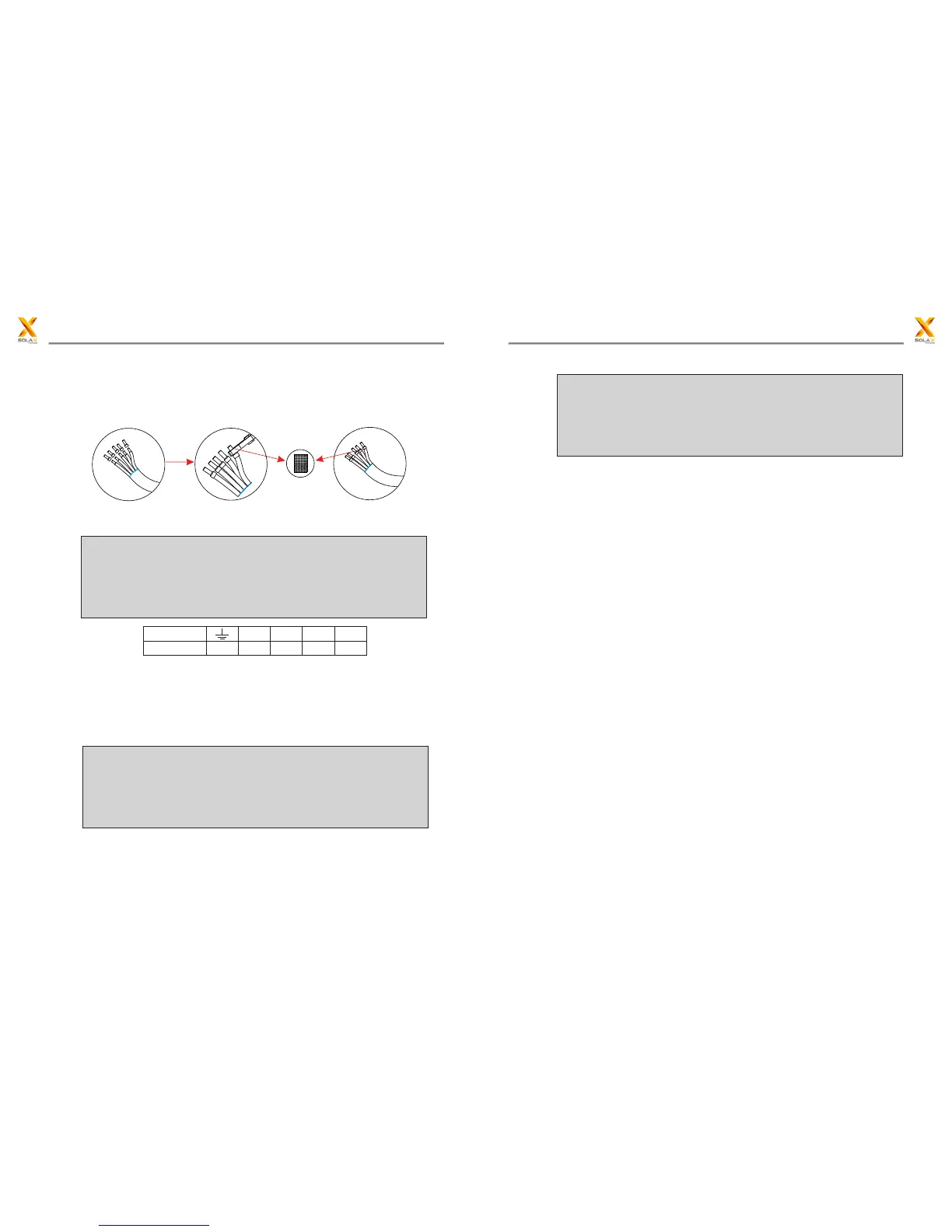
6. Insert striped cable into AC terminal and insure all conductor strands are
captured in the AC terminal. Compress the AC terminal head by using a
crimping pliers and screw down screw cap tight.Cable core section after
crimp should be the section as below.
7. Insert the tripped end of each ve wires into the appropriate hole in the
female insert,and then tight each screw(to tight each wire in place).
NO.of holes
Wire type
1
N
2
R
3
S
4
T
PE
8. Tight the cable
a. Slide the back shell towards the female insert.
b. Holde the middle part of the female insert,rotate the back shell to connect
it to the female insert and tight it.
c. Slide the cable nut towards the back shell.
d. Rotate the cable nut to secure the cable.
9. Connect the AC plug to the inverter,and then rotate the locking ring of the
female insert to screw the plug to the inverter.
Selection of Fuses and Cables
Mains cable (AC line cable ) shall be short circuit protected and thermal overload
protected.
Always fit the input cable with fuse. Normal gG(US:CC or T) fuses will protect
the input cable in short circuit situation. They will also prevent damage to
adjoining equipment.
Dimension the fuses according to local safety regulations,appropriate input
voltage and the related current of the solar inverter.
AC output protected by external fuse (gG rated current 25A/250VAC for 10KW
and 12KW; 32A/250VAC for 15KW,17KW and 20KW) provide in all live connections
to the AC supply.
The rated short circuit breaking capacity of the above protective device shall
be at least equal to the prospective fault current at the point of installation.
See section technical data of this manual for details.
Ac output cable: Cu, L, N+PE,2*6 .0+6.0mm @40°C ambient with a max length
of 5m , with operating time of the fuse is less than 5 seconds, installation method
B2 according to EN60204-1:2006, annex D: cable in conduit cable trunking system,
number of loaded circuit only one . Use H07RNF (cord designation 60245 IEC66)
for an ambient temperature of 40 °C or less and use 90°C wire for ambient
temperature beween 40°C and 60°C.
Note1: For conditions differing form those mentioned above ,dimension the
cables according to local safety regulations, appropriate input voltage and the
load and the load current of the unit.( You can choose a thicker cable but the
fuses must rated according to the cable.)
Note2: Fuses must be approved by Notified Body.
Inverter is not provided galvanic isolation from the mains to the PV array, backfeed
current to the array is 25A/250VAC for 10KW and 12KW; 32A/250VAC for15KW,
17KW and 20KW based on the fuse provided in the mains. Also in the worst
case .the reverse current comprises the sum of the short-circuit currents of
all intact lines.
Therefore the current-carrying capacity of the components and sub-assemblies
provided in the end-use system(connectors ,cables, junction box, switch ger,etc.).
and the reverse current PV module shall be considered based on the backfeed
25
24
5 Installation5 Installation
 Loading...