RS485 Connection Steps:
Ø
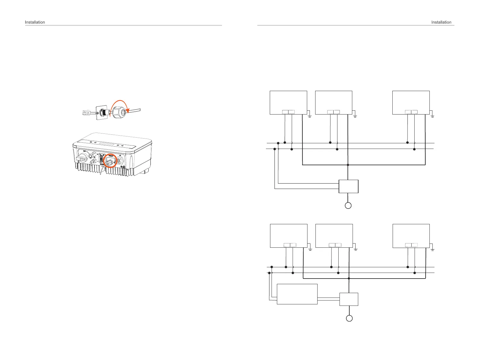
1) Firstly unscrew the screw from the COM/CT port. (PH1 cross
screwdriver. Torque: 1.0±0.1N.m)
2) Prepare a communication cable and strip the insulation from it.
3) Let the communication cable pass though the waterproof connector,
then insert it into the connector following the PIN definition rule.
34
35
Hand tighten.
Torque:1.2±0.1N.m
Parallel connection
The series inverter provides the parallel connection function, which could
support several inverters to parallel in one system and can control zero
injection to the grid with a meter installed in the main circuit.
The parallel system can be achieved with Modbus Function or with Datahub.
Please refer to the following diagrams.
Diagram B: Parallel system with Datahub
Diagram A: Parallel system with Modbus Function
...
~
Grid
Meter/CT
Master
Inverter
Slave 1
Inverter
Slave N
Inverter
Datahub
~
Grid
Meter
Slave 1
Inverter
Slave 2
Inverter
Slave N
Inverter
Modbus cable
DC
485_A
485_B
AC
DC
AC
DC
AC
DC
AC
DC
AC
DC
AC
...
485_A
485_B
485_A
485_B
485_A
485_B
485_A
485_B
485_A
485_B

 Loading...