36
37
Ø Parallel system with Modbus Function
In this parallel system, at most 5 inverters can be connected. One inverter
will be set as a master, and the rest are the slaves. The master inverter can
communicate with all the slave inverters.
a) Connect all the inverters in the parallel system with each other via RS485
cables.
b) Connect the communication cable with the master inverter.
Ÿ Wiring operation
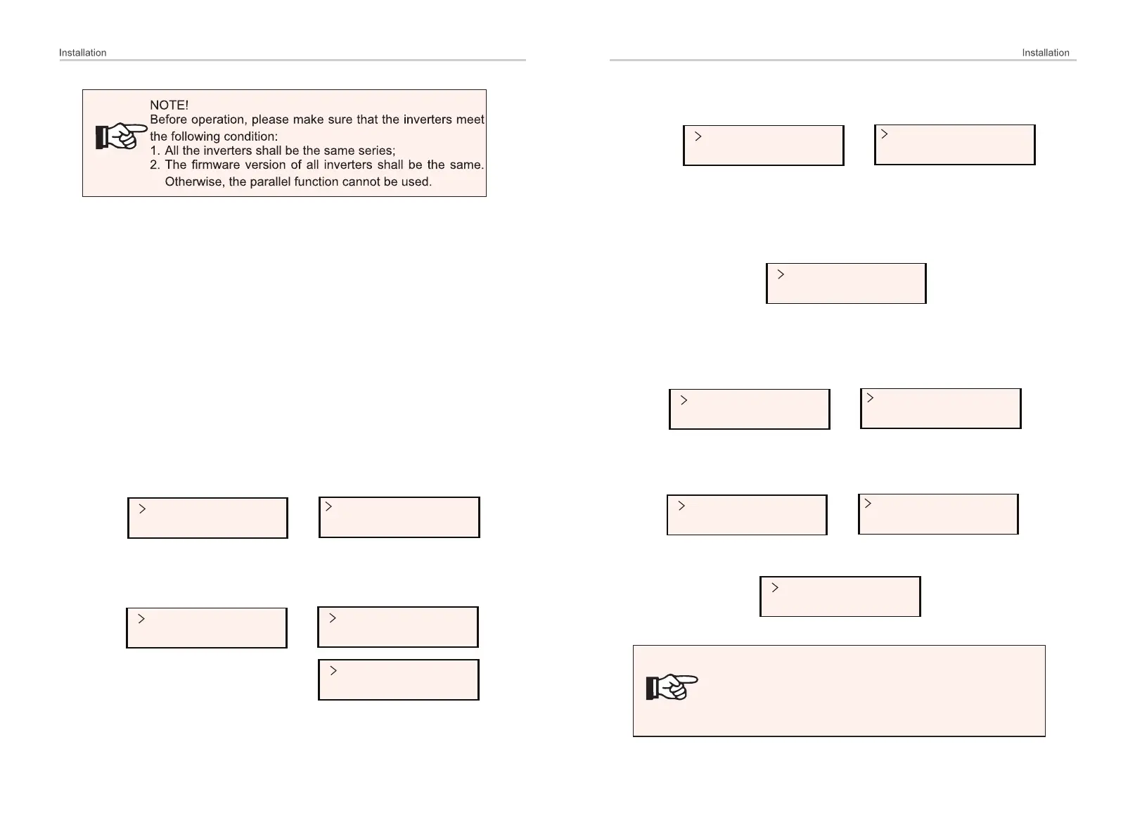
Ÿ Setting
Export Control
DRM Function
Parallel Switch
Enable
ParallelSetting
MpptScanMode
Turn on the power of the entire system, enter setting page of the inverters
on the LCD screen. Follow the instructions below to finish the settings.
To set the master inverter:
a) Enter “ParallelSetting” page, choose “Enable” to activate the function
for the inverter.
Mode Select
CT
Mode Select
Meter
b) Make sure the meter/CT is connected to the master inverter. Enter the
“Export Control” page and choose “Meter”/“CT” on the master inverter.
NOTE!
The power limit value set in “System Limit” is the limit for the
multiple inverters in the parallel system, while the “UserValue” set
in “Export Control” is the power limit for a single inverter which will
be nullified when the parallel function is enabled.
c) Choose “M/S Mode” to select the Master inverter. Only one inverter can
be set as “Master”.
M/S Mode
Master
M/S Mode
System Limit
d) Set the value for “System Limit” on the master inverter. This will be the
overall power limit for parallel system. The output power of slaves will then
be distributed respectively according to their nominal output power. The
value can be set within the range of 0 kW to 30 kW and the default value
is 0 W.
System Limit
0
Mode Select
Disable
Export Control
DRM Function
To set the slave inverters:
a) Enter “Export Control” page, and the mode status is “Disable” by default
(users cannot set by themselves).
b) Choose “ParallelSetting” and then set the status of “Pallel Switch” as
“Enable”.
Parallel Switch
Enable
ParallelSetting
MpptScanMode
c) Enter “M/S Mode” and chose “Slave” to set the Slave inverters.
M/S Mode
Slave

 Loading...