38
39
For the details, please refer to the user manual of Datahub.
NOTE!
The parallel system with Modbus Function and the EV-Charger
function cannot be used at the same time currently. If the
EVCharger is connected when multiple inverters are working in
the parallel system:
When the “ParallelSetting” is enabled, the inverter
communication with EV-Charger would be interrupted. In this
case, the EV-Charger should have its own CT/Meter installed to
work properly with parallel inverters.
When the "ParallelSetting“ is disabled, the EV-Charger function is
enabled, then the EV-Charger can work normally with the inverter
it is connected to, while other inverters cannot realize the export
control function.
NOTE!
Before connecting the Datahub to the parallel system, please check
that the inverters' settings meet the following
conditions:
The “ParallelSetting” should be “Disable”.
The addresses of all the inverters should be different.
Otherwise, please reset the RS485 communication addresses.
The communication address of meter and inverter mustn’t be the
same, otherwise a conflict may arise.
NOTE!
The inverter connected with the Datahub should not enable
the “ParallelSetting”.
There is no need to set the “ParallelSetting” on the inverters, the
parallel system with Datahub will start automatically.
Ø
Ø
Parallel system with Datahub
In this parallel system, at most 60 inverters can be connected. The
Datahub will be the master of the system, and all the inverters are the
slaves. The Datahub can communicate with all the slave inverters.
Wiring operation
a) Connect one terminal of an RS485 communication cable with
Datahub, and the other end with one of the slave inverters.
b) Connect all the slave inverters with each other via RS485 cables.
c) Connect the meter with the Datahub and the mains.
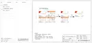
b. Meter (optional) connection
With this single phase meter working together with the inverter, you can:
(1) Monitor the energy to grid and from grid through the whole day.
(2) Achieve the export control function with a higher accuracy.
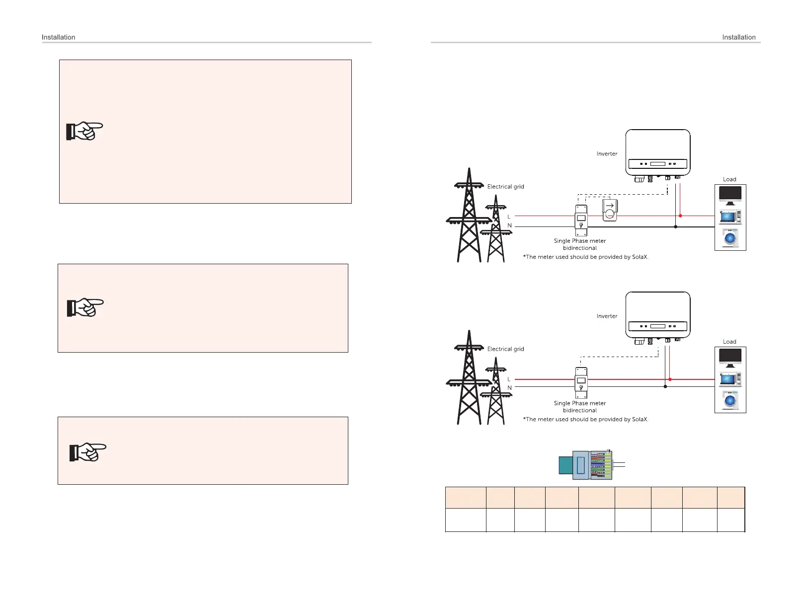
The PIN definition of Meter interface is shown as below.
4
5
i. For meter with CT
ii. For meter without CT

 Loading...