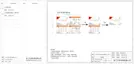
c. CT Connection:
CT connection diagram
The current sensor measures the current on the phase wire that runs between
the inverter and the grid.
1
8
40
41
CT PIN Definition
When connecting the RJ45 connector with the wire of the CT, please
follow the sequence below:
Meter Connection Steps:
Ø
Please see the Quick Guide and User Manual for Single Phase Meter
Installation for details.
Note!
It is recommended to connect our Smart meter to inverter. If there is no smart
meter installed, please disable the "Export Control" function in the inverter
setting otherwise the inverter will stop and report a "Meter fault" alert. The
“Export Control” is disabled by default, if an error occurs, please check if it is
disabled.
The smart meter must be purchased from and authorized by us, any third
party or non-authorized meter may not match with the inverter. We will not
take the responsibility if the meter is unavailable or incompatible in this case.
CT Connection Steps:
RJ45 connector
Screw cap
CT clamp
CT structural decomposition
communication line
• Do not place the CT on the N Wire or the earth wire.
• Do not place the CT on the N and L wire simultaneously.
• Do not place the CT with the arrow pointing to the inverter side.
• Do not place the CT on the non-insulated wires.
• Do not use the wire over 25m.
NOTE!
1. Insert the RJ45 connector of CT into the "RS485" port on the inverter,
and screw down the screw cap tightly.
2. Make sure the current sensor is installed in the right direction: The
arrow on the current sensor must point to the public grid.
3. Clip the CT clamp on L line from the home main meter box side.
4. Use electrical tape to prevent CT from falling off.

 Loading...