1. Prepare RJ45 connector and a communication cable.
2. Strip the insulation from the communication cable.
3. Let the communication cable pass though the waterproof plug, then
insert it into the RJ45 connector following the PIN definition rule.
4. Crimp the RJ45 connector with the crimping plier.
5. Insert the cable into the RS485 port of the inverter, and tighten the
waterproof plug.
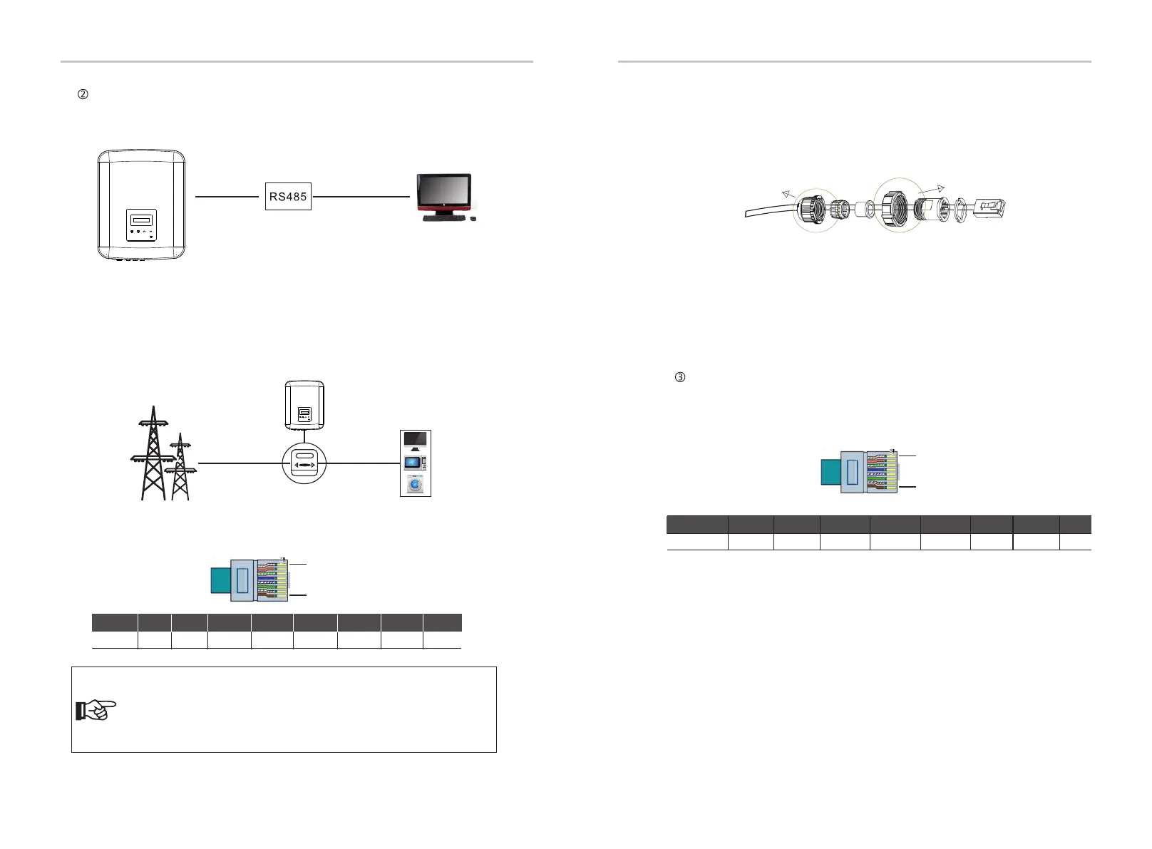
RS485/Meter
This is a communication interface provided for engineers to adjust the inverter.
a. RS485
b. Meter(optional)
1. Monitor the energy to grid and from grid throughout the whole day.
2. Achieve the export control function with a higher accuracy.
Please see the Quick Installation Guide for three-Phase Meter for details.
The PIN denitions of RS485/Meter interface are as below.
1
8
PIN
Definition
1 2 3 4 5 6 7 8
485_A
+12V
485_B
DRM0 RY-OUT
RS485 Connection Steps:
Meter Connection Steps:
Electrical
grid
Electric meter,
bidirectional
Load
X3-MIC G2 series inverter
1. Prepare RJ45 connector and a communication cable.
2. Strip the insulation from the communication cable.
3. Let the communication cable pass though the waterproof connector with
RJ45, then insert it into the RJ45 connector following the PIN definition rule.
4. Crimp the RJ45 connector with the crimping plier.
5. Insert the cable into the RS485 port of the inverter, and tighten the
waterproof connector.
DRM is provided to support several demand response modes by giving control
signals as below.
1
8
Pin
Definition
1
2
3 4
5
6
7
8
DRM0
DRM
Installation Installation
A meter can communicate with the X3-MIC G2 series inverter through this
interface, then you can:
Connection Steps:
Hand tighten. torque: 1.2±0.1N·mHand tighten. torque: 1.5±0.1N·m
Note!
The smart meter must be authorized by SolaX, any third party or
non-authorized meter may not match with the inverter.
SolaX will not take the responsibility if the unauthorized meter is
unavailable.
XX X X X
+12V
X
GND
NC NC
26
27
 Loading...


