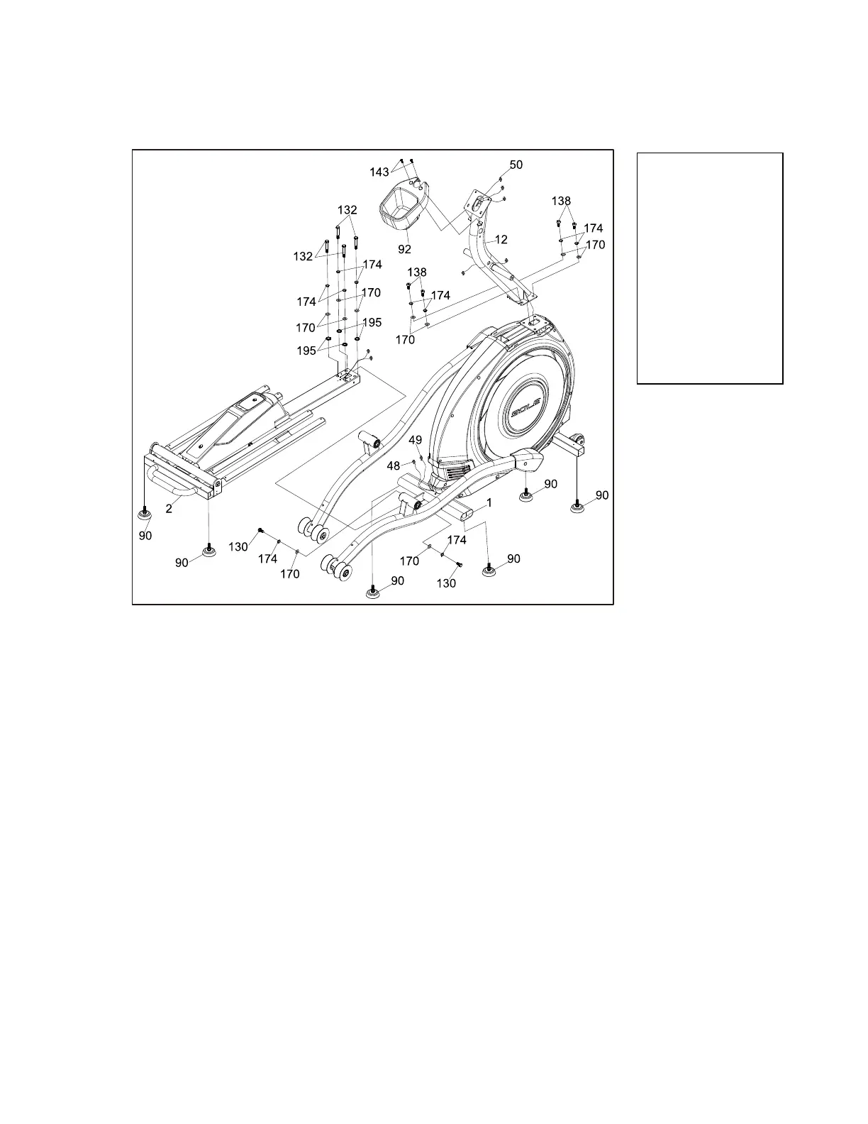
INCLINE RAIL AND CONSOLE
MAST
1. Install 6pcs Adjustment Foot (90) to the Front Stabilizer and Middle Stabilizer
of the Main Frame (1) and the Rear Stabilizer of the Incline Rail Assembly(2).
2. Install the Incline Rail Assembly (2) into the U-channel bracket of the Main
Frame (1). Secure with the four bolts & associated hardware as follows: From
the sides install 2pcs Hex Head Bolts (130) with 4pcs Hex Head Bolts (132),
6pcs Split Washers (174), 6pcs Flat Washers (170) and 4pcs Star
Washers(195), as shown in figure 1, and tighten with Wrench (183).
3. Connect the 3-wire harness: Incline Motor Power Cord (48) to the female
receiver cable coming from the Incline Rail Assembly (2). Connect the Three
pin position Sensor connector: Incline Motor Connecting Wire (49) to the
female receiver coming from the Incline Rail Assembly (2)
4. Run the Computer Cable (50) through the Console Mast (12), pull the
opposite end of this twist tie up through the Console Mast (12) until the cable
exits the top. Install the Console Mast (12) into the receiving bracket on the
top of the Main Frame (1). Install 4pcs Socket Head Cap Bolts (138) with 4pcs
Split Washer (174), and 4pcs Flat Washers (170) and tighten with the provided
L Allen Wrench (182). Pull slightly on the computer cable at the top of the
mast while installing. This will ensure the cable does not get pinched and
shorted during console mast assembly.
5. 4. Install the Bottle Holder (92) to the Console Mast (12) with 2pcs Phillips
Head Screws (143) and tighten with the provided Phillips Head Screwdriver.
(181).
Hex Head Bolt (2 pcs)
#132. 3/8" × 2"_
Hex Head Bolt (4 pcs)
#138. 3/8" × 3/4"_
Socket Head Cap Bolt
(4 pcs)
#143. M5 × 10mm_
Phillips Head Screw
(2 pc)
#170. Ø3/8" × Ø19 ×
1.5T_Flat Washer (10 pcs)
#174. Ø10 × 2T_
Split Washer (10 pcs)
#195. Ø10_Star Washer
E95 ASSEMBLY
INSTRUCTIONS