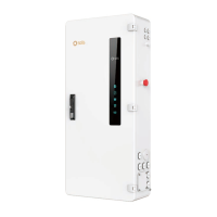
The Solis Hub-200A-US is a Microgrid Interconnect Device (MID) designed for photovoltaic (PV) battery, generator, grid, and home loads. It is engineered to work with Solis S6 hybrid inverters to provide smart controls and whole-home backup solutions.
Function Description
The Solis Hub-200A-US acts as a central control and interconnection point for various energy sources and loads within a microgrid system. Its primary function is to manage the flow of power between the PV system, battery storage, a generator, the utility grid, and the home's electrical loads. This enables features such as whole-home backup during grid outages, optimization of energy consumption, and integration of multiple power sources. The device facilitates smart controls, allowing for efficient energy management and enhanced system reliability.
Important Technical Specifications
The Solis Hub-200A-US is designed for robust performance and safe operation. Key technical specifications include:
Electrical Connections:
- Grid L1/L2: 1 AWG wire, 250 Lb.In torque, M14 Hexagonal Screwdriver.
- Neutral: 1 AWG wire, 250 Lb.In torque, M14 Hexagonal Screwdriver.
- AC Grid L1/L2: 6 AWG wire, 250 Lb.In torque, Slotted screwdriver.
- AC Backup L1/L2: 6 AWG wire, 250 Lb.In torque, Slotted screwdriver.
- Neutral (AC Backup): 6 AWG wire, 250 Lb.In torque, Slotted screwdriver.
- Load 1-4: 6 AWG wire, N/A torque, Slotted Screwdriver.
- Grid Load: 6 AWG wire, N/A torque, Slotted Screwdriver.
- Neutral (Load): 6 AWG wire, 250 Lb.In torque, Phillips screwdriver.
- Generator L1/L2: 6 AWG wire, N/A torque, Screwdriver.
Communication Interfaces:
- CAN: RJ45 Connector - Connect to the master inverter's Parallel_A port.
- ETHERNET: RJ45 Connector - Connect to the master inverter's SPH-IN Port.
- EPO IN/EPO OUT: Connect to the master inverter's EPO IN/EPO OUT to realize emergency power off function.
- Dry_Con_B / Dry_Con_A: If a remote remote motor is required, the generator remote start signal needs to be connected to the Dry_contact_A and Dry_contact_B.
- RS485A / RS485B: Reserved.
Display Indicators (LEDs):
- Running lights: Indicates if the system is running (ON) or not (No power).
- Inverter communication lights: Indicates if the inverter communicates normally (ON) or if it's unused/no inverter.
- Meter communication lights: Indicates if the meter is normal (ON) or if it's unused/not connected.
- Grid status: Indicates if there is grid access (ON) or no power grid/not connected.
- Generator status: Indicates if there is generator access (ON) or no generator/not connected.
Physical Dimensions:
- Height: Approximately 1100mm.
- Width: Approximately 500mm.
- Depth: Approximately 300mm (estimated from diagram).
Environmental:
- Grid input: Ø77.7
- Independent load output: Ø45.5
- Load output: Ø63
- Generator input: Ø63
- 200A load output: Ø77.7
Usage Features
The Solis Hub-200A-US is designed for ease of installation and operation, offering several features that enhance its usability:
Mounting:
- Drill holes: Use the mounting bracket as a template to drill holes for the mounting bracket. Ensure suitable expansion bolts are used to fix the bracket onto the wall.
- Mounting the Hub: Hang the Solis Hub onto the mounting bracket.
- Secure the Hub: Use three screws to fasten the Solis Hub with the mounting bracket.
AC Incoming Supply Connection:
- Remove cover: Remove the AC connection cover at the top of the Solis Hub.
- Insert AC cables: Insert the AC cables into the Solis Hub.
- Connect wiring: Connect Grid L1 / Grid L2 / Neutral wire to the corresponding terminals.
Hybrid Inverter Connection:
- Conduit routing: Use six conduits on the left side of the Solis Hub to run the Solis hybrid inverter's AC Grid Cable and AC Backup Cable into the Solis Hub.
Load Connection:
- Load AC wires: Lead the load AC wires from the conduits on the right side or bottom of the Solis Hub.
- Connect smart load terminals: Connect the corresponding loads to the smart load terminals (Load 1 – Load 4) or the non-backup load terminal (Grid Load). Use a slotted screwdriver and insert the square port on the left side of the terminal, then insert the AC wire to the round port on the right side of the terminal. Release the screwdriver to fasten the wires.
- Connect neutral wire: Connect the load neutral wire to the neutral bar terminal.
Generator Connection:
- Bring AC cables: Bring the AC cables for the generator into the Solis Hub from the right side.
- Strip insulation: Strip 3/8 inch of insulation from the ends of each cable.
- Insert into terminal: Insert a technician screwdriver into the small hole on the wire terminal.
- Fasten terminal: Pull the screwdriver to the right side to fasten the terminal and then release the screwdriver.
- Test connection: Give the wire a gentle tug to ensure it is tight. If the wire feels loose, repeat steps 3-5.
Safety Features:
- Emergency stop switch: Allows for immediate shutdown of the system in case of an emergency.
- Overcurrent protection: Integrated fuses and circuit breakers protect against overcurrent conditions.
- Grounding: Proper grounding ensures electrical safety.
Maintenance Features
The Solis Hub-200A-US is designed with features that facilitate maintenance and troubleshooting:
Package List for Replacement Parts:
- GL.WB10.004.004: Accessory bag (Key) - 1 unit.
- 2501700.07-LDPE: Ziplock bag - 1 unit.
- 3.2: Key - 1 unit.
- GL.WB10.00.005: Accessory bag (backplane screws) - 1 unit.
- 2501700.07-LDPE: Ziplock bag - 1 unit.
- T20-M4*16-SS-C1-φ12: Flower-shaped pan head screw assembly M4*16 - 2 units.
Troubleshooting via LED Indicators:
- Running lights: If off, indicates no power, prompting a check of the main power supply.
- Inverter communication lights: If off, indicates the inverter is not communicating, suggesting a check of inverter connections or status.
- Meter communication lights: If off, indicates the meter is not communicating, suggesting a check of meter connections or status.
- Grid status: If off, indicates no grid power, prompting a check of the utility grid connection.
- Generator status: If off, indicates no generator access, prompting a check of the generator's connection or operational status.
Accessible Terminals:
- The design allows for easy access to all wiring terminals for inspection, tightening, or replacement.
Modular Design (Implied):
- While not explicitly stated, the component breakdown and package list suggest a modular design, which simplifies the replacement of individual parts if needed.
Contact Information for Support:
- Company: Ginlong Technologies Co., Ltd.
- Address: No. 57 Jintong Road, Binhai Industrial Park, Xiangshan, Ningbo, Zhejiang, 315712, P.R. China.
- Tel: +86 (0)574 6578 1806
- Fax: +86 (0)574 6578 1606
- Email: info@ginlong.com
- Web: www.solisinverters.com
This comprehensive description covers the functionality, technical specifications, usage, and maintenance aspects of the Solis Hub-200A-US, providing a clear understanding of its role in a microgrid system.