3. Installation 3. Installation
.17..16.
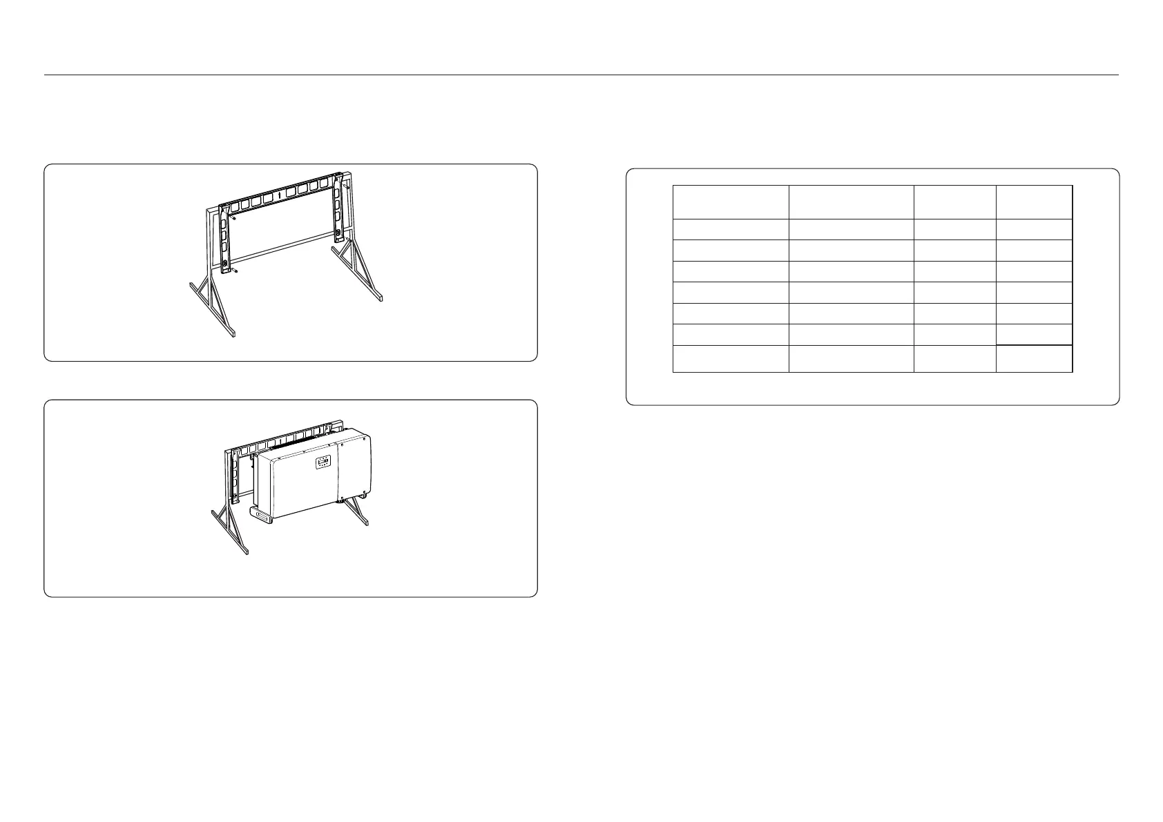
4) Lift the inverter above the bracket and then slide down to make sure they match perfectly.
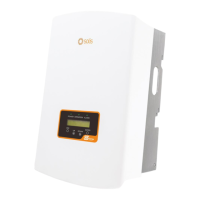
Figure 3.13 Construction bolt
Figure 3.14 Mount the inverter
3) Align the mounting plate with the holes, insert the combination bolt (M10X40)through the
mounting plate into the hole. Secure the bracket to the metal frame firmly with the supplied
fastener. Torque the nut to 36FT-LB (35NM).
3.4 Electrical Connections
The electrical connection of the inverter must follow the steps listed below:
1. Switch the Grid Supply Main Switch (AC) OFF.
2. Switch the DC Isolator OFF.
3. Connect the inverter to the grid.
4. Assemble PV connector and connect to the Inverter.
Inverter design uses PV style quick-connect terminal. The top cover needn't be opened
during DC electrical connection. The labels located the bottom of the inverter are described
below in table 3.1. All electrical connections are suitable for local or national standard.
Table 3.1 Electrical connection symbols
Parts
Connection Cable size
Torque
DC terminal
Ground terminal
Grid terminal
RS-485 terminal
RJ45 terminal
COM terminal
PV strings
AC ground
Grid
Communication cable
Communication cable
Wi-Fi/Cellular stick
DC surge protection
device
NA
4-6mm²
25-50mm²
50-185mm²
0.3-4mm²
Network Cable
NA
0.6N.m
NA
NA
NA
NA
NA
10-20N.m
10-12N.m
 Loading...