25
Chapter 2 Hardware Setup
nV
ID
IA
nF
O
R
C
E
2
DIM1
IDE2
IDE1
L
i
B
a
t
t
e
r
y
F
a
n
3
nVIDIA
nFORCE2
AC'97
Codec
WOL1
1
S
P
K
R
S
T
K
e
y
l
o
c
k
H
D
D
/
L
E
D
I
R
T
X
/
I
R
R
X
P
W
R
S
M
I
+
+
-
-
1
PCI1
PCI5
PCI4
PCI3
PCI2
Audio1
14
USB3
1
10
FD1
1
DIM2
PW1
S
O
C
K
E
T
4
6
2
RT2
DIM3
1
1
CDIN1
DDR 400/333/266MHz
RTL
ALC650
Fan2
1
Jp1
AGP1
IDE3
BIOS
PD
C
20376
PW2
1
Jp2
R
T
1
J
B
A
T
1
1
1
Jp4
SATA1
SATA2
1
Jp5
(nFORCE2 SPP)
MCP
Fan1
LPC I/O
W83627HF
NJP1
1
1 1
Master Dual Channel DIMM slot
U
ltra 400
LPT1
COM1
PS/2
Mouse
(on top)
PS/2 Keyboard
(underside)
RJ45
(on top)
USB3
USB2
L
i
n
e
i
n
(on top)
L
i
n
e
O
u
t
(
m
id
d
le
)
M
i
c
(
u
n
d
e
r
s
id
e
)
USB0
(on top)
USB1
COM2
+12V Power
JAUD1
1
1
Jp7
(underside)
(middle)
ATX Main Power
USB0
(on top)
(underside)
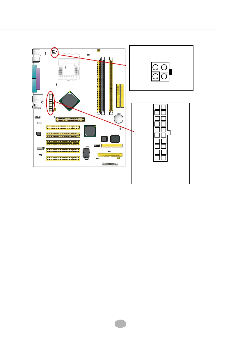
2-7 ATX Power Supply Installation
+12V Power
Connector
ATX V2.03 Power Supply is strongly recommended running with the
nFORCE2-chipset mainboard.
To set up Power Supply on this mainboard:
1. Get ready a V2.03 ATX Power Supply which provides a square-shaped
+12V Power Connector in addition to the 20-pin Main Power
Connector and other peripheral power connectors.
2. Connect the on-board square-shaped +12V Power Connector to the
square-shaped +12V Power Connector of the Power Supply.
3. Connect the on-board 20-pin Main Power Connector to the 20-pin
Main Power Connector of the Power Supply. Please note that both
the +12V Power Connector and the 20-pin Main Power Connector
should be connected to Power Supply to power on the system.
GND
+12V
1
3
GND
+12V
24
+12V
5SB
PWR OK
GND
GND
GND
GND
GND
GND
+5V
+5V
-5V
+5V
+5V
+3.3V
+3.3V +3.3V
PS ON#
Pin1 Pin11
-12V
GND
Main Power Connector
(20-pin)