35
Chapter 2 Hardware Setup
nV
ID
IA
nF
O
R
C
E
2
DIM1
IDE2
IDE1
L
i
B
a
t
t
e
r
y
F
a
n
3
nVIDIA
nFORCE2
AC'97
Codec
WOL1
1
S
P
K
R
S
T
K
e
y
l
o
c
k
H
D
D
/
L
E
D
I
R
T
X
/
I
R
R
X
P
W
R
S
M
I
+
+
-
-
1
PCI1
PCI5
PCI4
PCI3
PCI2
Audio1
14
USB3
1
10
FD1
1
DIM2
PW1
S
O
C
K
E
T
4
6
2
RT2
DIM3
1
1
CDIN1
DDR 400/333/266MHz
RTL
ALC650
Fan2
1
Jp1
AGP1
IDE3
BIOS
PD
C
20376
PW2
1
Jp2
R
T
1
J
B
A
T
1
1
1
Jp4
SATA1
SATA2
1
Jp5
(nFORCE2 SPP)
MCP
Fan1
LPC I/O
W83627HF
NJP1
1
1 1
Master Dual Channel DIMM slot
U
ltra 400
LPT1
COM1
PS/2
Mouse
(on top)
PS/2 Keyboard
(underside)
RJ45
(on top)
USB3
USB2
L
i
n
e
i
n
(on top)
L
i
n
e
O
u
t
(
m
id
d
le
)
M
i
c
(
u
n
d
e
r
s
id
e
)
USB0
(on top)
USB1
COM2
+12V Power
JAUD1
1
1
Jp7
(underside)
(middle)
ATX Main Power
USB0
(on top)
(underside)
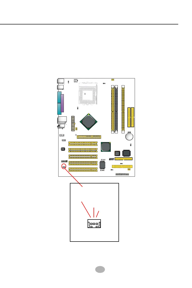
2-9.7 Wake On LAN Connector:
1. This connector connects to a PCI LAN card with a Ring signal output.
The connector powers up the system when it receives a wake-up
packet or signal through the LAN card.
2. This feature requires that Resume On Ring feature is enabled in the
BIOS setting “Power Management Setup” and that your system must
be on ATX power supply with at least 720mA / +5V standby power.
Connect the Wake On LAN
signal from LAN card to WOL1
WOL1
Ring
GND
+5V
Standby