31
Chapter 2 Hardware Setup
n
V
ID
IA
n
F
O
R
C
E
2
DIM1
IDE2
IDE1
L
i
B
a
t
t
e
r
y
Fan3
nVIDIA
nFORCE2
AC'97
Codec
WOL1
1
S
P
K
R
S
T
K
e
y
l
o
c
k
H
D
D
/
L
E
D
I
R
T
X
/
I
R
R
X
P
W
R
S
M
I
+
+
-
-
1
PCI1
PCI5
PCI4
PCI3
PCI2
Audio1
14
USB3
1
10
FD1
1
DIM2
PW1
SOCKET 462
R
T
2
DIM3
1
1
CDIN1
DDR 400/333/266MHz
RTL
ALC650
Fan2
1
Jp1
AGP1
ID
E3
BIOS
PD
C
20376
PW2
1
Jp2
R
T
1
J
B
A
T
1
1
1
Jp4
SATA1
SATA2
1
Jp5
(
n
F
O
R
C
E
2
S
P
P
)
MCP
Fan1
LPC I/O
W83627HF
NJP1
1
1 1
Master Dual Channel DIMM slot
U
ltra 4
00
LPT1
COM1
PS/2
Mouse
(on top)
PS/2 Keyboard
(underside)
RJ45
(on top)
USB3
USB2
L
i
n
e
i
n
(
o
n
t
o
p
)
L
i
n
e
O
u
t
(
m
id
d
le
)
M
i
c
(
u
n
d
e
r
s
id
e
)
USB0
(on top)
USB1
COM2
+12V Power
JAUD1
1
1
Jp7
(underside)
(middle)
ATX Main Power
USB0
(on top)
(underside)
2-9 Other Connectors Configuration
This section lists out all connectors configurations for users’ reference.
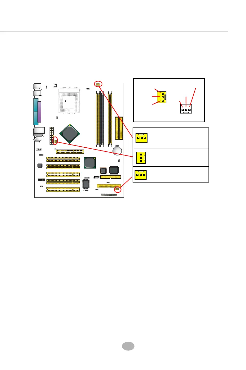
2-9.1 Onboard FAN Connectors
FAN1, Sensor Fan Connector
(Yellow)
FAN2, Sensor Fan Connector
(Yellow)
FAN3, Sensor Fan Connector
(Yellow)
Sensor Conn.
No Sensor
Void
+12V
GND
Sensor
+12V
GND
Both Sensor and No-sensor Fan Connectors support CPU/AGP/Sys-
tem/Case cooling fan with +12V mode. A Hardware Monitor chipset is
on board, with which users can install a Hardware Monitor Utility and
read the fan speed transmitted from the sensor fan. Otherwise, users
can read the fan speed from the “Hardware Monitor Status” via BIOS.
A running Fan will send out 2 electric pulses per rotation of its fan
blade. A Sensor Fan Connector will count the electric pulses and send
the information to the System Hardware Monitor which in turn will work
out the fan rotation speed and display it on screen.


 To Next Page