3
EN
Copyright © 2014 - 2015 Somfy SAS. All rights reserved. Non contractual images.
These instructions are mandatory for the home motorisation and automation
professional who installs the S&SO-RS100 io drive.
Never drop, knock or puncture the drive or immerse it in liquid.
Install an individual control point for each drive.
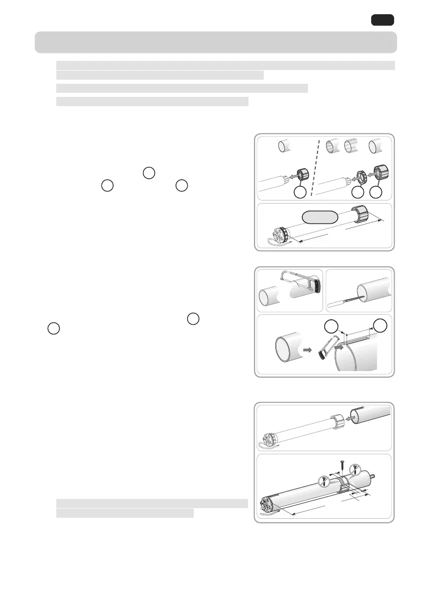
2.1. ASSEMBLY
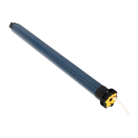
2.1.1. Drive preparation
1) Mount the accessories needed for integration of
the drive into the winding tube:
Either only the wheel
a
on the drive.
Or the ring
b
and the wheel
c
on the drive.
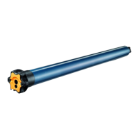
2) Measure the length (L1) between the inside edge
of the drive head and the end of the wheel.
2.1.2. Tube preparation
1) Cut the winding tube to the desired length
depending on the product to be motorised.
2) Deburr the winding tube and remove all chips.
3) For winding tubes that are smooth inside, cut a
notch to the following dimensions:
d
= 4 mm;
e
= 28 mm.
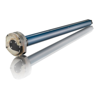
2.1.3. Drive-tube assembly
1) Slide the drive into the winding tube. For winding
tubes that are smooth inside, position the cut
notch on the protruding part of the ring.
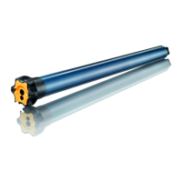
2) The wheel must be locked in a straight line inside
the winding tube:
Either by securing the winding tube to the wheel
using 4 Ø 5 mm Parker screws or 4 Ø 4.8 mm
steel pop rivets located between 5 mm and
15 mm from the outside edge of the wheel,
irrespective of the type of winding tube.
The screws or pop rivets must only be fastened
on the wheel and not on the drive.
Or by using a wheel lock, for non-smooth tubes.
1
1
1
1)
L1
L1 = …
2)
Ø > 47 mm
cb
Ø = 47 mm
a
3)
1) 2)
d
e
15 mm
5 mm
L1
1)
2)
1
2. INSTALLATION
 Loading...