Page 17
2.2.1.2 Inputs for Model 305 Only
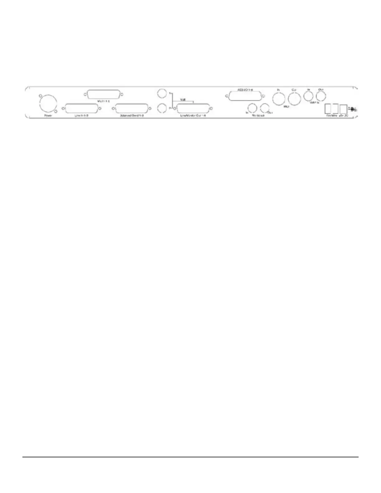
You may connect microphones directly your Model 305 Converter by attaching an analog DB25
to XLR male cable assembly to the inputs labeled “Mic In 1-8.”
Attach the power cord, but do not power up your converter at this time.
Figure 1 — Model 304 Back Panel Configuration
2.2.2 Digital Audio Connections
All Series 300 models support eight channels of AES Type I or balanced digital audio–over–
copper connections.
2.2.2.1 Input For All Models
For AES/EBU digital input, use the digital DB25 cable assembly you connected earlier to your
unit’s AES connector labeled “AES I/O 1-8,” and attach the XLR female connectors to the out-
puts of your outboard AES device(s). These are associated with digital inputs 1-8, Digital In
1-Digital In 8, of soundBlade.
2.2.2.2 Output For All Models
For AES digital output, connect your digital DB25 cable assembly to your unit’s AES connector
labeled “AES I/O 1-8,” then attach the four XLR male connectors to the inputs of your outboard
AES device(s). These are associated with the digital outputs of soundBlade.
2.2.2.3 Output for Model 304 and 305 Only
Use the 1/4” balanced TRS “Multi” outputs to connect your unit to a stereo input on your
mixer, typically the main stereo input. The top connector is channel 1 or Left, usually being fed
from Mix Bus M1 in soundBlade, while the bottom connector is channel 2 or Right, which is
usually being fed from Mix Bus M2 in soundBlade.
Note: This is the same output signal you will find present on channels 1 and 2 of the associated
multichannel DB25 connector labeled “Line/Monitor Out 1-8.”
Connect your analog DB25 cable assembly to the “Line/Monitor Out 1-8” on the back of your
converter. This is the DB25 connector in the center of the unit’s back panel, and it is fed from
the Mix Buses M1-DAW 1 through M8-DAW 8 in soundBlade.
Using the connectors that are appropriate for your mixer, plugging them into eight input
channels on your mixer. This set up provides for the monitoring of the M1-M8 outputs in