Page 32
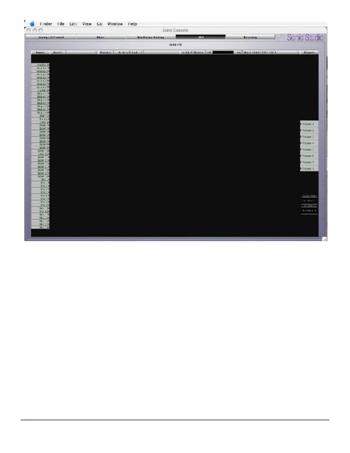
Figure 6 — The +DSP pane
The +DSP pane includes a number of elements. The large dark area with the grid is the
“Graph.” On the left of the Graph are the input ports. On the right are the output ports repre-
senting process buses that make the processed signal available for routing and patching in the
Mix/Output Routing pane.
Along the top of the Graph area are a number of controls that you use to configure the signal
processing. Right next to the “Insert:” label is the Process menu. To the right of the “Patches:”
label is the Graph Configuration menu that lets you save and recall Graph states. Continuing
horizontally is a DSP load meter, while next to the DSP load meter is a DSP menu. These are all
described below.
3.2.1 DSP Menu
The DSP menu lists the available DSPs in the system. There should be one for each +DSP box
you have attached to your computer. They will be listed by box type, serial number, and DSP
number. All the +DSP units have one available DSP (DSP #1). The software is capable of ad-