Page 29
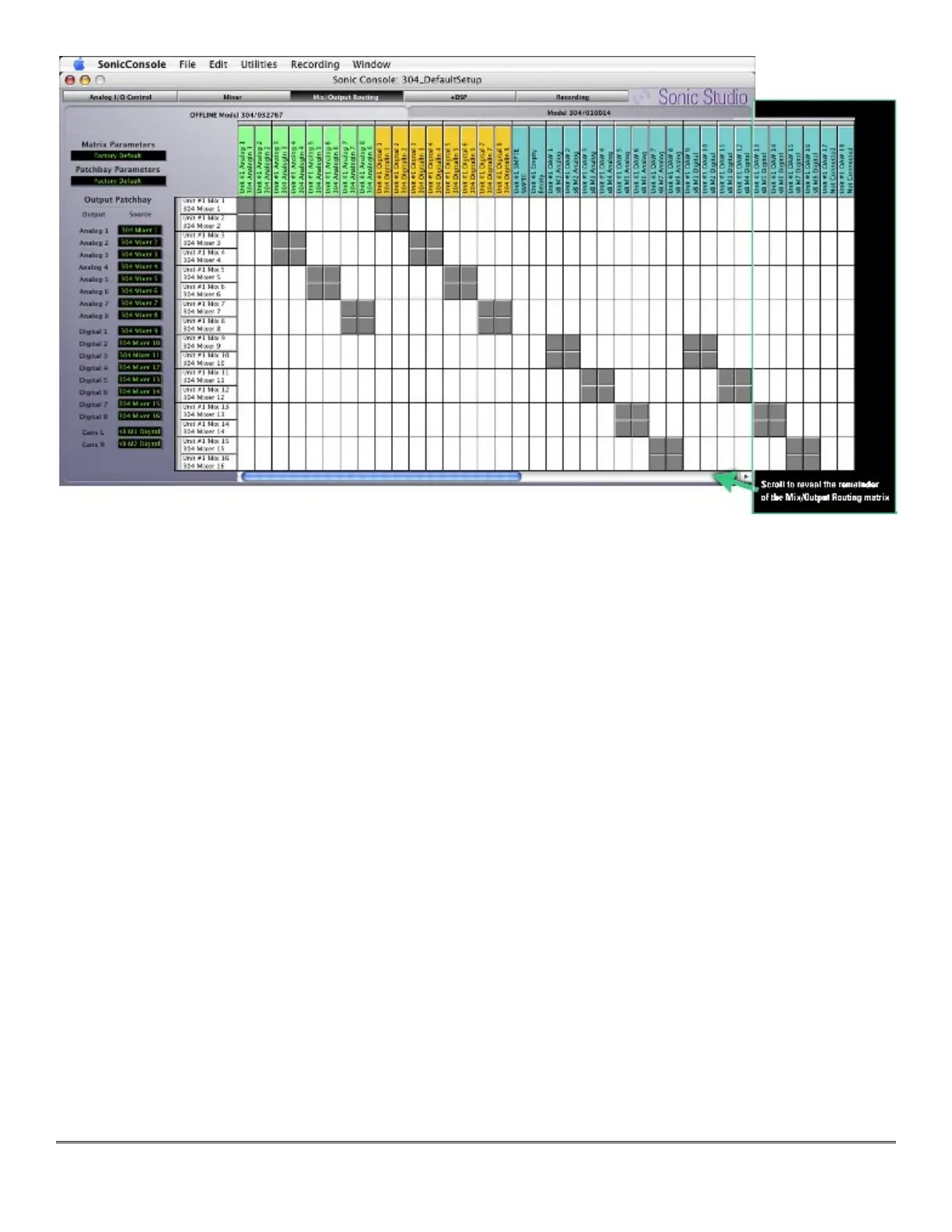
Figure 4 — The Mix/Output Routing pane
In the the I/O matrix, each mix bus and each input channel has a labeled header associated
with it. Column headers are arrayed along the top and left edges of the matrix, with row head-
ers arrayed along the left side. The columns, with their colored header labels, are the various
sources available from which a signal can be patched, while the rows, with their white headers,
represent the Sonic Console internal mix buses to which sources can be patched.
Columns of the same type are grouped by header color:
Green for analog inputs
Gold for AES digital inputs
Teal for soundBlade mix buses and outputs
Magenta for ADAT digital inputs
Each header displays the Series 300 unit with which it is associated, when multiple units are
operating in parallel, along with the default name of the bus, and the user defined name for
that bus. Double click on a header to change its user defined name.
Associated with the outside edge of each pair of headers is a gray bar that is used to couple or
link two buses into a stereo pair. If buses are linked into a stereo pair and the pair is assigned
to an internal mix bus, the pair will be represented in the Mixer pane by dual mono faders with
pan pots
•
•
•
•