12
Instruction for use | Supercal 739
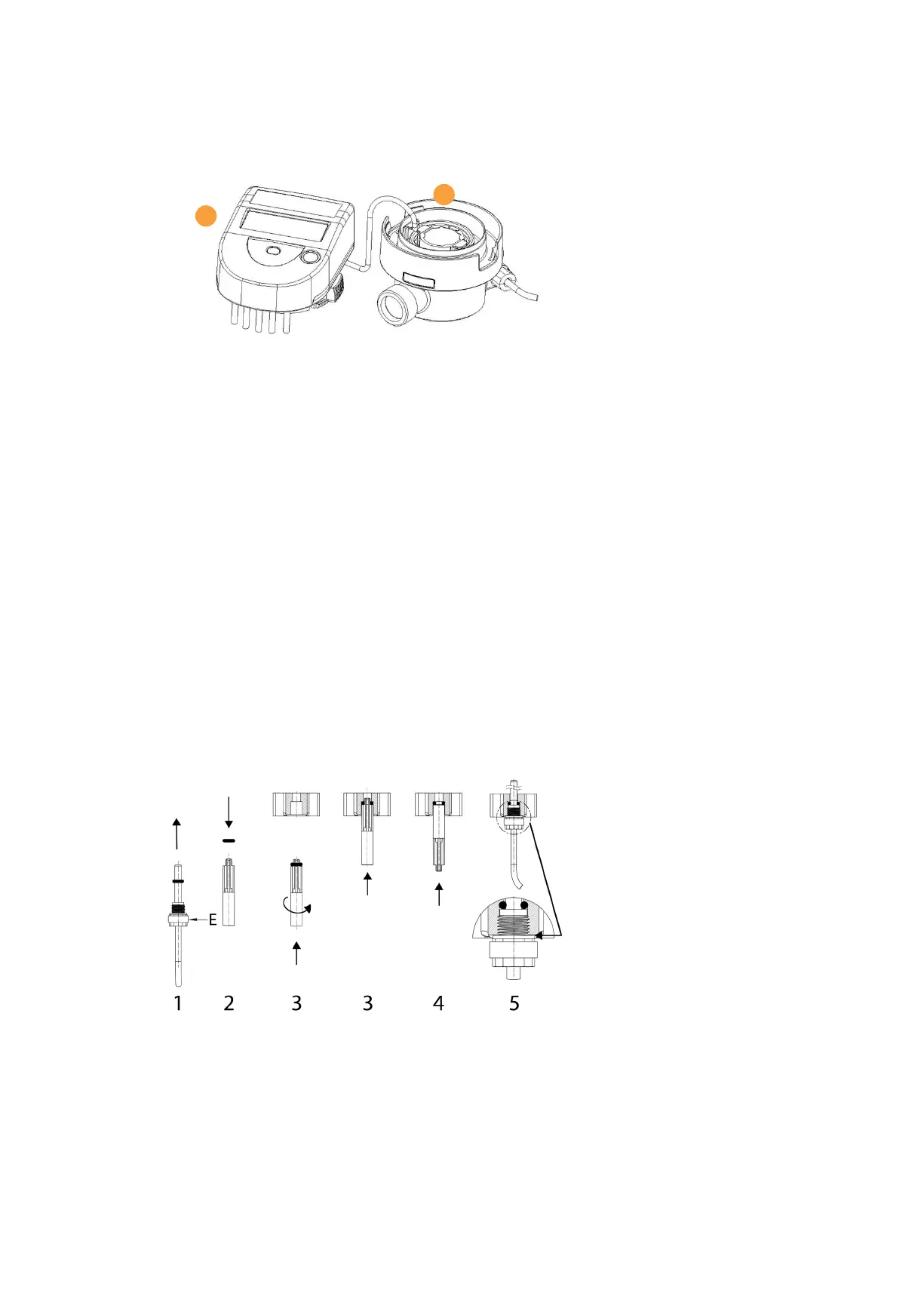
To remove the calculator from the wall support, it will be sufcient to press laterally on the two
locking buttons while pulling the assembly towards you.
Rewind the connection cable at the position provided for this purpose on the ow meter (1) and
reinsert the calculator (2).
6.3 Mounting of the temperature sensors
The temperature sensor in the ow meter has no black frame marking on the label.
The temperature sensor with the black frame mark on the label indicates that the sensor must
be mounted in the pipe “opposite” to the Supercal 739.
Example: If the ow meter is installed on the warm side (Hot Pipe), the temperature sensor with
the black frame mark will be mounted in the cold side (Cold Pipe).
The Supercal 739 is delivered with temperature sensors having a cable length of 1.5 m.
The temperature sensors form a sub-assembly with the calculator. The temperature sensor
cables must be neither shortened nor lengthened.
The temperatures of use displayed on the label must be respected.
A temperature sensor may be tted directly in the Supercal 739 ow meter. The temperature
sensors will preferably be tted directly, in other words one temperature sensor will be tted in
the ow meter while the other sensor will be installed on the other side of the heat exchanging
circuit.
Note: The temperature sensors will be xed with a plastic nut. This plastic nut consists of two
half-nuts held together by a rubber band. If the rubber band is removed from the nut, the two
nut halves will no longer be held together on the temperature sensor and one or both nut halves
may separate from the temperature sensor.
1. Remove the O-ring from the temperature sensor. Be careful not to remove the rubber band
(symbolized by the letter "E" on the drawing) from the nut as it may separate into two parts
and fall on the oor.
2. Fit the O-ring on the mounting template pin.
3. Insert the O-ring by rotating it using the tting template in the position provided for the ball valve.
4. Position the O-ring denitively with the other at end of the tting tem-plate.
5. Insert the temperature sensor with the two half-nuts in the thread M10x1 of the ball valve
and screw down by hand as far as it will go (maximum tightening torque of 1 Nm).
Note: The mounting template pin is not included in the delivery and can be ordered separately
(Article number: 0460P348).
1
2
 Loading...