CJ)
f-
z
UJ
::;
f-
(/)
:::,
-,
0
<:
..;
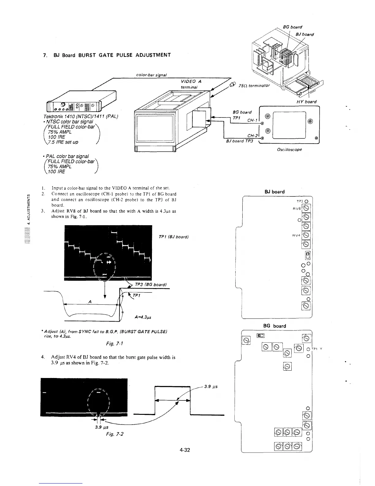
7. BJ Board BURST GATE PULSE ADJUSTMENT
Tektronix 1410 (NTSC)/1411 (PAL)
• NTSC color bar signal
(
FULL FIELD color-bar)
75%AMPL
100 IRE
7.5 IRE set up
• PAL color bar signal
(
FULL FIELD color-bar)
75%AMPL
100 IRE
color-bar signal
I. Input a color-bar signal to the VIDEO A terminal of the set.
2. Connect an oscilloscope (CH-I probe) to the TP! of BG board
and connect an oscilloscope (CH-2 probe) to the TP3 of BJ
board.
3. Adjust RV8 of BJ board so that the with A width is 4.3µs as
shown in Fig. 7-1.
VIDEO A
TP1 (BJ board)
* Adjust (A), from SYNC fall to B.G.P. (BURST GATE PULSE)
rise, to 4.3µs.
Fig. 7-1
4. Adjust RV4 of BJ board so that the burst gate pulse width is
3.9 µs as shown in Fig. 7-2.
---~ 1=39µ,
3.9 µs
Fig. 7-2
4-32
HY board
BGboard D
TP1 CH-1 •@ @
CH-21 @
BJ board TP3
Oscilloscope
BJ board
BG board
TPJ Q
Rvst:QJ
o[Q]
I~
RV4~
[Q]
~
oo
0
~
~
0
[Q]
@)