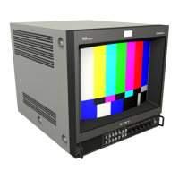
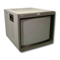
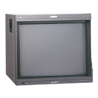
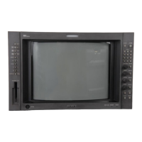
Do you have a question about the Sony BVM-2011P and is the answer not in the manual?
Details how to assign input signals to the front panel input selectors via the menu.
Explains how to set and store phase, chroma, brightness, and contrast levels in registers.
Describes how to store and select white balance settings in registers.
Details the procedure for setting, changing, and applying a password to restrict menu access.
Details how to specify installed optional boards, signal configurations, and monitor types.
Adjusts the convergence for 4:3 aspect ratio normal scan mode.
Adjusts the monitor's white balance at lowlight and highlight levels using test signals.
Matches the monitor's black reference to the input signal's black level for accurate display.
Describes the input circuit, including cable compensation and hook-up circuits.
Describes the luminance signal circuit, including filter and aperture control.
Explains switching circuits for Y, crosshatch, setup, R-Y, G-Y, B-Y signals, and AGC pulse insertion.
Explains the processing of the 1H pulse from composite sync signals.
Explains the 3-line dynamic comb filter for chroma and luminance separation.
Details the chroma band pass filter used in the PAL system.
Describes the chroma band pass filter for the NTSC system.
Details the vertical deflection output amplifier and boost-up circuit.
Describes the AC power supply and rectifier circuit, including voltage selection.
Provides a general overview of the convergence system and its basic principles.
Details the horizontal delay function and H AFC circuit for stable scanning.
Describes the horizontal deflection output circuit, including driver and output transistor.
Describes how high voltage applied to the CRT anode is detected and converted.
Illustrates the physical location of various circuit boards within the monitor.
Details the steps for landing adjustment, including DY and neck assembly positioning.
Explains how to adjust the focus control for optimal picture sharpness.
Describes static convergence adjustments using DCT and BMC magnets.
Details the dynamic convergence adjustment for 4:3 aspect ratio pictures.
Explains the dynamic convergence adjustment for 16:9 aspect ratio pictures.
Procedure for adjusting and storing white balance settings using test signals and meters.
Adjusts chroma and phase levels using preset menu and front panel controls.
Adjusts the BRT pulse waveform on the BJ board using an oscilloscope.
Adjusts the SUMPRING PULSE waveform on the BJ board using an oscilloscope.
Adjusts the input signal level on the BA board using an oscilloscope.
Adjusts the input circuit frequency characteristics on the BA board.
Adjusts the frequency characteristics of the BG board using CV1, CV2, and CV3.
Adjusts the component input signal levels on the BG board using RV21 and RV22.
Adjusts the burst gate pulse width on the BJ board using RV8 and RV4.
Adjusts the band pass filter on the BC board using L3.
Adjusts the phase shift on the BC board using the front panel PHASE control and RV3.
Adjusts the 3.58MHz frequency on the BC board using CV2.
Adjusts the color difference phase on the BC board using oscilloscope and RV2.
Adjusts the color difference levels on the BC board using RV4 and RV5.
Adjusts the Y trap on the BC board to minimize the 3.58MHz subcarrier.


 Loading...