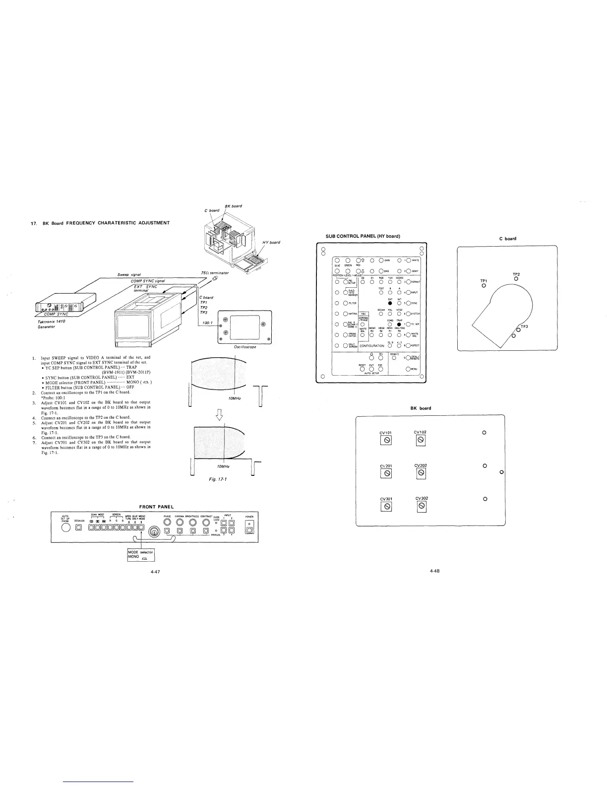
17. BK Board FREQUENCY CHARATERISTIC ADJUSTMENT
Tektronix 1410
Generator
Sweep signal
1. Input SWEEP signal to VIDEO A terminal of the set, and
input COMP SYNC signal to EXT SYNC terminal of the set.
• YC SEP button (SUB CONTROL PANEL)··· TRAP
(BVM-1911) (BVM-2011P)
• SYNC button (SUB CONTROL PANEL)····· EXT
• MODE selector (FRONT PANEL)············· MONO ( .=.)
• FILTER button (SUB CONTROL PANEL)··· OFF
2. Connect an oscilloscope to the TPl on the C board.
*Probe: 100:1
3. Adjust CV101 and CV102 on the BK board so that output
waveform becomes flat in a range of O to 10MHz as shown in
Fig. 17-1.
4. Connect an oscilloscope to the TP2 on the C board.
5. Adjust CV201 and CV202 on the BK board so that output
waveform becomes flat in a range of O to 10MHz as shown in
Fig. 17-1.
6. Connect an oscilloscope to the TP3 on the C board.
7. Adjust CV301 and CV302 on the BK board so that output
waveform becomes flat in a range of O to 10MHz as shown in
Fig. 17-1.
FRONT PANEL
AUTO
SET UP
PROBE
0
DEGAUSS
!
MODE selector I
MONO-=.
4-47
BK board
75n terminator
C board
TPT
TP2
TPJ
100:1
@
®D
@)
Oscilloscope
HY board
@)
@
10MHz
l
D
10MHz
Fig. 17-1
POWER
0
0
0
SUB CONTROL PANEL (HY board)
0
r=---=---___,---------~o
0 0 OD o OG;JN
0 1QWHITE
BLUE GREEN RED
0 0
0
0
0
0
0
0
o~~~F
COMBS
0 CROSS
HATCH
oi~~lEN
0 QBIAS
D1 RGB YUV CODED
0
0 0 0 3OFORMAT
TEST B A
0 0 0 •Q1NPUT
EXT INT
e O sQsYNC
SECAM PAL NTSC
0 0 O sQsYSTEM
CHROMA
/PHASE
COMB TRAP
0 0
•
1QYc SEP
WHITE
MEM3
MEM2
MEMl
D65/D93
BAL
R3
R2
Rl RO
0 0 0 0 0
aQ~E
16: 9
4: 3
CONFIGURATION
0
0
90ASPECT
()
SEL
REMOTE
0
0
oQ~f~
RESET
ENT
ESC
0
0
0
OMENU
AUTO SETUP
0
BK board
CV101
CV102
[Q]
~
CV201
CV202
[Q]
~
CV301
CV302
~
~
4-48
TPl
0
0
0
0
C board
0
TP2
0
OTP3
0