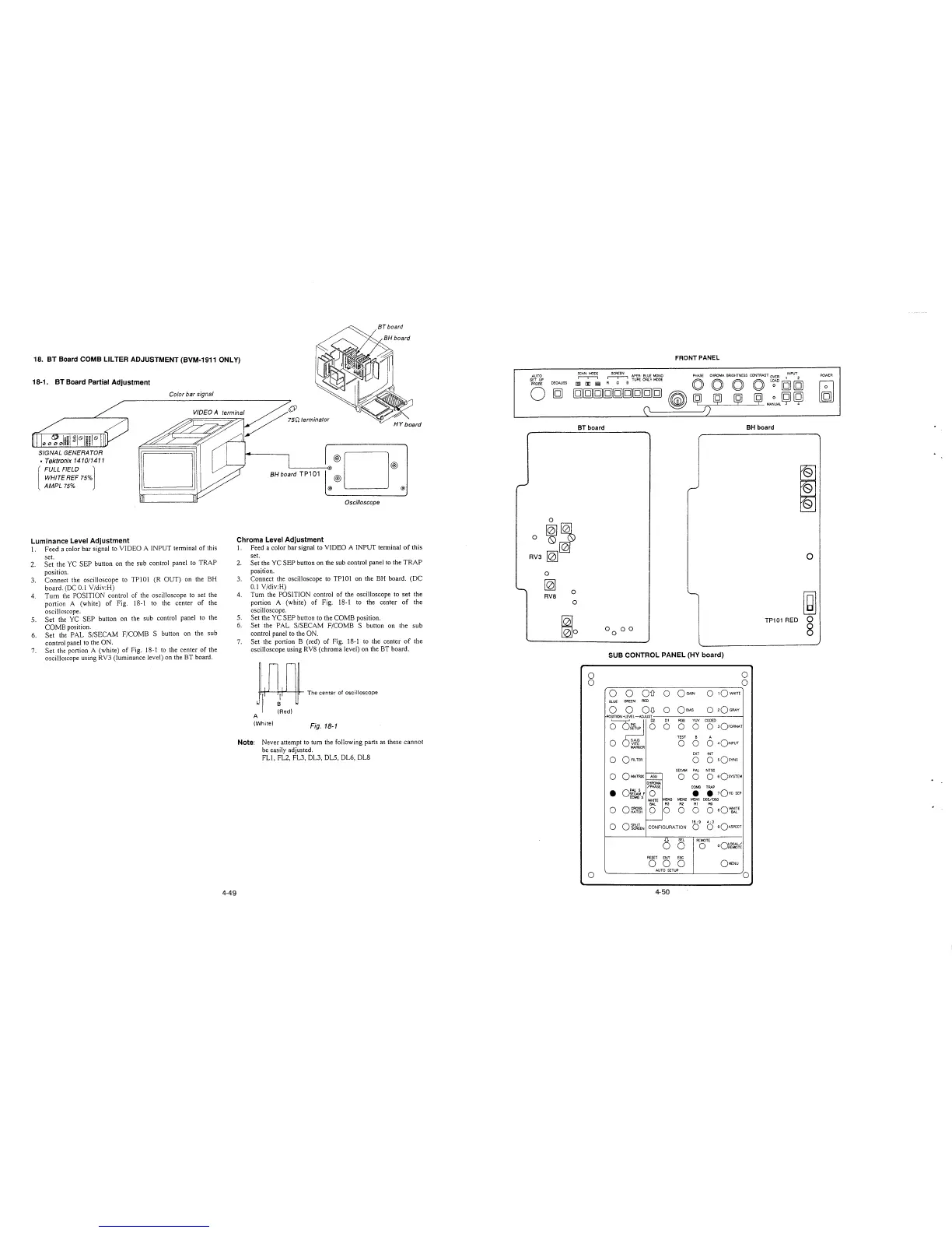
18. BT Board COMB LILTER ADJUSTMENT (BVM-1911 ONLY)
18-1. BT Board Partial Adjustment
SIGNAL GENERATOR
, Tektronix 141011411
[
FULL FIELD l
WHITE REF 75%
AMPL 75%
Luminance Level Adjustment
Color bar signal
VIDEOA
l. Feed a color bar signal to VIDEO A INPUT terminal of this
set.
2. Set the YC SEP button on the sub control panel to TRAP
position.
3. Connect the oscilloscope to TPlOl (R OUT) on the BH
board. (DC 0.1 Y/div:H)
4. Tum the POSITION control of the oscilloscope to set the
portion A (white) of Fig. 18-1 to the center of the
oscilloscope.
5. Set the YC SEP button on the sub control panel to the
COMB position.
6. Set the PAL S/SECAM F/COMB S button on the sub
control panel to the ON.
7. Set the portion A (white) of Fig. 18-1 to the center of the
oscilloscope using RV3 (luminance level) on the BT board.
4-49
BH board TP101
·®D®
@
@) @)
Oscilloscope
Chroma Level Adjustment
1. Feed a color bar signal to VIDEO A INPUT terminal of this
set.
2. Set the YC SEP button on the sub control panel to the TRAP
position.
3. Connect the oscilloscope to TPlOl on the BH board. (DC
0.1 V/div:H)
4. Turn the POSITION control of the oscilloscope to set the
portion A (white) of Fig. 18-1 to the center of the
oscilloscope.
5. Set the YC SEP button to the COMB position.
6. Set the PAL S/SECAM F/COMB S button on the sub
control panel to the ON.
7. Set the portion B (red) of Fig. 18-1 to the center of the
oscilloscope using RYS (chroma level) on the BT board.
Wl,
~
The center of oscilloscope
(Red)
A
(White)
Fig. 18-1
Note: Never attempt to turn the following parts as these cannot
be easily adjusted.
FL!, FL2, FL3, DL3, DL5, DL6, DLS
AUTO
SET UP
PROBE
DEGAUSS
FRONT PANEL
~
SCREEN APER- BLUE MONO PHASE CHROMA. BRIGHTNESS CONTRAST OVER l INPUT
2
0
(gJ [D i,;i
~
TURE ONLY ~DE O O O O L~AD [g [g
[g[g[g[g[g[g[g[g[g
~
~
ij ij ij ~~UAL~
~
(\
~
L__r_') -'-----'-----'--
0
0
~~
0~
RV3
~
0
~
0
RVB
0
~o
BT board
0
0
0
BH board
SUB CONTROL PANEL (HY board)
0
0
0
0
OD 0
OGAJN
0
1QWH1TE
BLUE
GREEN
RED
0 0 O~
0
Qs1AS
0
2Q GRAY
POSITION -LEVEL-ADJUST
o ~c
01 RGB YUV CODED
0 0
0
0 3OFOR~T
TEST
B A
0 S.A.D.
0
0 0
401NPUT
VITC
MARKER
EXT INT
0
oflLTER
0 0
sQsvNc
SECAM PAL NTSC
0
o~TRIX
-
ASU
0 0
o sQsYSTEM
CHRO~
/PHASE
COMB TRAP
•
o:~~F
0
•
• 1Qvc SEP
COMB 5
MEMJ MEM2 MEM! 065/093
WHITE
BAL
R3 R2 Al RO
0
0~~5~
0 0 0 0
0 aQ~rE
-
16; 9 4; 3
0
OSPLIT
CONFIGURATION
0
o sQAsPECT
SCREEN
6
SEL
REMOTE
0
0
oQ~Cf~¼
RESET
ENT ESC
0 0
0
QMENU
AUTO SETUP
0
4-50
0
~
TP101 RED 0
8
POWER