3-5. SYNC PROCESSOR, PULSE GENERATOR
(BJ BOARD)
3-5-1. 1H Pulse Processing
The composite sync is separated from incoming signal at BA board.
And I H sync is made by separating V sync and equalizing pulse
from composite sync.
Also H sync which has constant pulse width is made from I H
sync.
3-5-2. 2fH Multivibrator
This circuit generates 2fH rate pulse from H rate flyback pulse.
3-5-3. Vertical Counter
The 2fH rate pulse is counted down to generate Vertical rate trigger
pulse for vertical deflection circuit.
When there is no incoming signal, trigger pulse is generated by
vertical counter (384H).
When there is incoming signal with V sync, this counter circuit is
reset by V sync and generates trigger pulse synchronized with V
sync.
Also in order to increase stability of vertical scanning. noise gating
process is made during V sync period.
3-5-4. V Sync and Delay
V sync and V BLANKING pulses are generated by output trigger
pulse from vertical counter.
And when V DELAY SW on the front panel is selected ON, these
pulses are generated in a V/2 delayed position relative to the V
sync position of incoming signal.
3-5-5. Crosshatch Generator
Internal crosshatch signal is made as follows.
The vertical lines are generated by approx. I8fH rate pulses syn-
chronized with flyback pulse.
And tlyback pulse is counted down to generate horizontal lines.
3-5-6. Burst Gate Pulse, Y-CLAMP Pulse, C-CLAMP Pulse
Generator
The Burst Gate Pulse (B.G.P.), clamp pulse for luminance signal
(Y .CL.P} and clamp pulse for color difference signal (C.CL.P} are
generated from I H sync via LCR network and transistors.
3-5-7. Picture Set Up Pulse Generator
This is the gate pulse generator for picture set-up function, and
consists of mono multipliers.
3-5-8. Split, Y Blanking, C Blanking Pulse Generator
Y BLANKING pulse (Y BLK P) and C BLANKING pulse (C BLK P)
are generated. These pulses are used for the purpose of DC restora-
tion of color difference signal, Y signal and RGB signal. DC restora-
tion is made by inserting the black reference signal during blanking
period in the signal. Also C. BLK. pulse is mLxed with vertical rate
blanking signals for SPLIT display and for B/W display.
3-5-9. Horiiontal Rate AGC and Clamp Pulse Generator
COLOR GAIN control, CONTRAST control and BRIGHTNESS
control are stabilized by insertion of reference signal and using
feedback circuit. Horizontal rate BLACK pulse (B.P), BLACK
CLAMP pulse (B.CL.PJ and WHITE CLAMP pulse (W. CL.P) are
ienerated here.
3-9
3-5-10. Vertical Rate AGC and Clamp Pulse Generator
In this model, BEAM CONTROL circuit is used for high stability
in white balance.
The reference signal is inserted in the signal for gain control circuit
in video output amplifier and for beam control circuit. Vertical
rate pulses are used for this purpose.
Vertical rate BEAM PULSE (BM.P) DRIVE PULSE (DRIVE.Pl and
BEAM CLAMP PULSE (BM.CLP) are generated here.
3-5-11. Others
Black reference is determined at the position of clamping in black
reference insertion circuit for both color difference signal and
RGB signal. Accordingly C.CL.P is used as clamp pulse for color
difference signal processing and Y.CL.P is for RGB signal. CLAMP
PULSE SELECTION SW switches C.CL.P. or Y CLP to the clamp
pulse for the insertion of black reference.
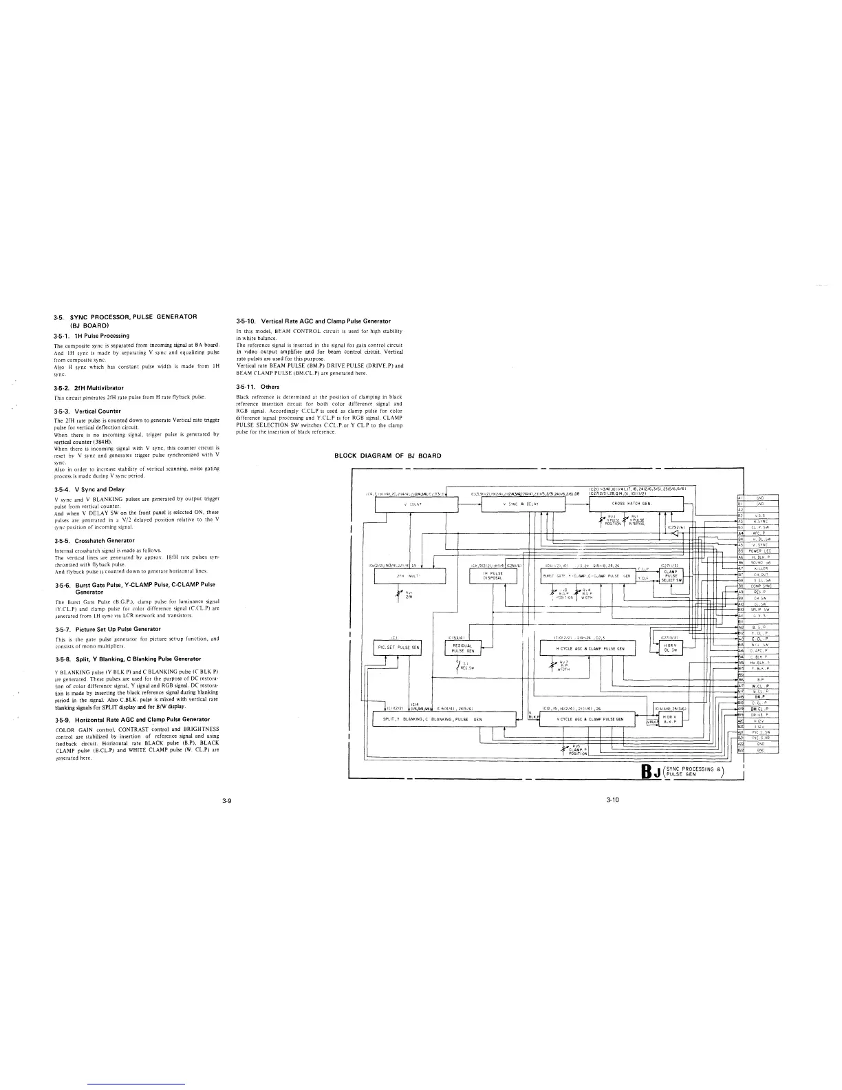
BLOCK DIAGRAM OF BJ BOARD
-
-
-
IC 211-3/41, 1611/41, 17, 18, 2412/6 ,3/61, 2515/6,6/61
IC 4, 1, I ':::I( 1141, 2C, Zl(4l41,2d2/4,3A~ !C.:' 3{3/ .3)
1(3,5,911121, 1912/41 2112A ""'2214/41 2311/3,2/31,2411/6,2/61,08
IC2712/3 I ,28, Q 14 ,DI, I Cll 1I/21
l
v cou~ T
I
i Cb( 212 l, !9(3/4l,221114 l
[,,q
I
2 f H MUL T'
t
~;~
,CI
I
PIC. SET PULSE GEN I
t
r
! ICI 1(2/2)
ICl4
I 1/4 3/4 4141
I
SPLIT, Y BLANKING, C
I
I
~
A I
V SYNC a Oti.. AY
CROSS HATCH GEN.
I
I
Bl
A2
t
B2
ff RV3 ltl RVI
H PulSE H PULSE
POSITION INTERVAL
A3
IC2512/bl 83
A4
-
i-----c._
B4
~AS
85
I
A6
ICt' ,9(2121, l':H414) 1(25(1/6) ICE:! I/ 2), 10(
•JIS-I8, 25, 26
L_
Bb
, 13, 2':!
IC27( 1/3)
I
l
C _(..._P
M
I H PULSE
I y CLF
CLAMP
DISPOSAL
BIJRS T GATF.
Y - C.AMP, C - CLAMP PULSE
GEN PULSE
87
!
SELECT SW A8
}
L_
--
BB
,f R,4
-
A9
8.G P
I
NIOTH
89
10
Bl
All
1B11
I( 1314/4 I I
Al2
1,
IC 1012121 , ,,19-24 , 02 3
~'""'"
r--
l
Al3
RESIDUAL
HORV
~
13
PULSE GEN
H CYCLE AGC & CLAMP PULSE GEN
DL SW
Al4
l
14
7 ,,
t RJ7
Al
RES. SW
8 p
WI 0TH
81'
lb
8'6
17
81
AIB
I ICI613/4) 2513/61
18
1(•614/41, 2415/61 ICI2,I5,I612/41, 2111/41 ,26
,---AI9
~
~
~AIS
p
[
~
HOR V
~
BLANKING, PULSE
GEN
V CYCLE AGC & CLAMP PULSE GEN
VBLK B_K,P
=
I
62(
~AZI
~B.21
,<~C~A'SP. P
AZ,
8Z
POSIT! ON
BJ
(
SYNC PROCESSING &)
PULSE GEN
-----------------==--
3-10
GND
GND
V. S .S
H. SINC
CL. I-' SW
AFC. P
H. DL .:::iw
V. SYNC
POWER LEC
H. BLK_ P
:,0/60 o>/1
K, LLER
CH. OL T
V CL. :::,N
COMP SYNC
RES P
CH SN
DL.':>W
SPLIP SW
G. V
s
8. ::, . p
Y. CL . P
C.Cl .P
N!v
o>/1
C.AFC,P
C BL< c
HV BLK.
~
Y. 8LK p
B P
W.CL
p
B.Cl
p
BM.P
C. CL
p
BM CL. P
DR I VE F
+ 12 V
+ !2 v'
PIC S .SW
PIC S.VR
GND
GNC