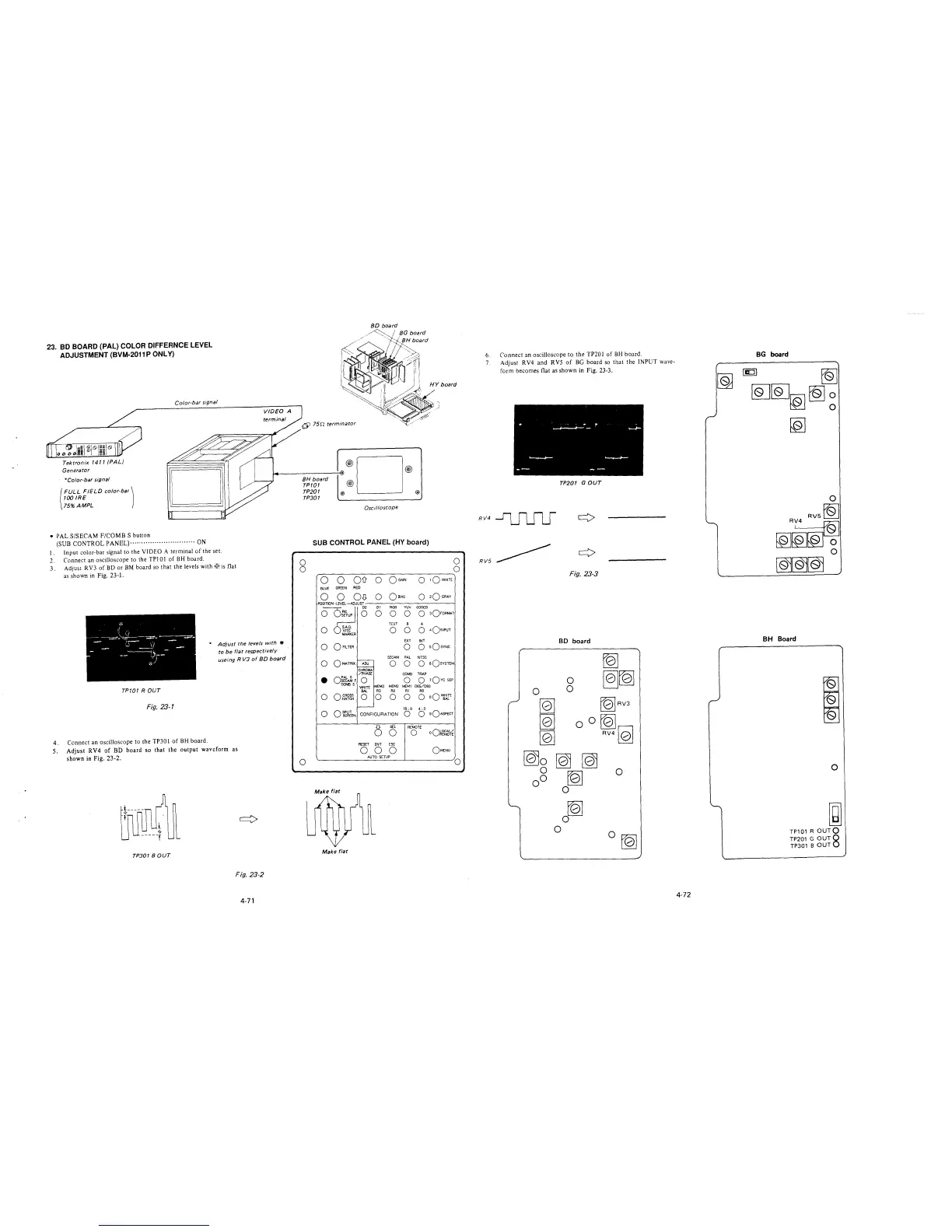
23. BO BOARD (PAL) COLOR DIFFERNCE LEVEL
ADJUSTMENT (BVM-2011 P ONLY)
Tektronix 1411 /PAL)
Generator
*Color-bar signal
(
FULL FIELD color-bar!
IOOIRE
75% AMPL
• PAL S/SECAM F/COMB S button
Color-bar signal
(SUB CONTROL PANEL)··················"··"····· ON
I. Input color-bar signal to the VIDEO A terminal of the set.
2. Connect an oscilloscope to the TPJ O 1 of BH board.
3. Adjust R V3 of BD or BM board so that the levels with w is flat
as shown in Fig. 23-1.
* Adjust the levels with •
to be flat respectively
useing R VJ of 8D board
TP701 ROUT
Fig. 23-1
4. Connect an oscilloscope to the TP30 l of BH board.
5. Adjust RV4 of BD board so that the output waveform as
shown in Fig. 23-2.
TP301 BOUT
Fig. 23-2
4-71
~
75D terminator
BH board
TP/01
TP201
TP301
®D®
@
@ @
Oscilloscope
SUB CONTROL PANEL (HY board)
'
)
0
0
0
0
0
~----------------~
Q Q QD- 0 QcA1N
0 1QWHITE
BLUE GREEN RED
0 Q OJJ O QmAS
0
0
0
•
0
0
o:~A~ F
COMBS
OCROSS
HATCH
OSPUT
SCREEN
Make flat
01 RGB YW CODED
0 0 0 0 3QroRMAT
TEST 8 A
0 0 0 4O1NPUT
EXT INT
O o sQsYNC
SECAM PAL NTSC
O O O sQsvsm1
CHROMA
/PHASE
COMB TRAP
0 0 0
1Qvc SEP
'Mi!TE
MEM3 MEM2 MEM1 065/093
BAL
R3
R2
Rl RO
0 0 0 0 0
aQ~rE
16: 9 4: 3
CONFIGURATION
0
0
sQASPECT
6
SEL
REMOTE
0
0
oQ~r~¼
RESET
ENT ESC
0 0 0
QMENU
AUTO SCTUP
0
6. Connect an oscilloscope to the TP201 of BH board.
7. Adjust RV4 and RVS of BG board so that the INPUT wave-
form becomes flat as shown in Fig. 23-3.
TP201 GOUT
RV4~
RV5~
Fig. 23-3
BD board
~
~[QJ
tb!RV3
fQ]
RV410l
0
tQ]
0
0
0 rQ]
4-72
BG board
~
~~~~~
[QJ
BH Board
I
'
'
0
~
TP101 R OUTQ
TP201 G OUT8
TP301 BOUT