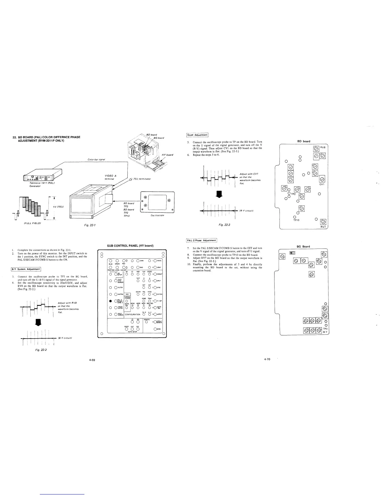
22. BD BOARD (PAL) COLOR DIFFERNCE PHASE
ADJUSTMENT (BVM-2011 P ONLY)
Color-bar signal
Tektronix 1411 (PAL)
Generator
1
-,-
1V (75n/
U ____ ,_
(FULL FIELD/
Fig. 22-1
1. Complete the connections as shown in Fig. 22-1.
2. Turn on the power of this monitor. Set the INPUT switch to
the I position, the SYNC switch to the INT position, and the
PAL S/SECAM F/COMB S button to the ON.
[ 8-Y System Adjustment I
3. Connect the oscilloscope probe to TP3 on the BG board,
and turn off the U (B-Y) signal of the signal generator.
4. Set the oscilloscope sensitivity to 20mV/DIV, and adjust
RV8 on the BD board so that the output waveform is flat.
(Sec Fig. 22-2.)
•
Adjust with R VB
i- so that the
waveform becomes
flat.
l
"r-~+--+-...,....,-~~: /B-Y circuit/
11 '
Fig. 22-2
4-69
0
0
0
VIDEO A
terminal
6) 75n terminator
BG board
TP3
BO board
TP2
TP10
@)
®D
®
Oscilloscope
SUB CONTROL PANEL (HY board)
0
0
0 0
Oil
0
OGAIN
0
1QWHITE
BLUE
GREEN
RED
0
0
O-G
0
Oe1AS
0
2OGRAY
RGB YW CODED
0
0
0 3OFORMAT
TEST 8 A
0
0 0 0
4o!NPUT
EXT INT
0
0 0
sOsYNC
SECAM
PAL
NTSC
0 0 0
o sQsvSTEM
CHROMA
/PHASE
COMB TRAP
•
Of~,
0
0
0 1Qvc SEP
COMBS
WHITE
MEM3 MEM2
MEM1 065/093
BAL R3
R2
Rl
RO
0
0 CROSS
HATCH
0 0 0
0
0 eQ~E
0 o~~lEN
CONFIGURATION
16: 9
0
4: 3
0
sQASPECT
0
SEL
REMOTE
0
0
oQ~~
RESET
ENT
ESC
0 0 0
OMENU
AUTO SETUP
0
@)
@)
5.
6.
Connect the oscilloscope probe to TP on the BD board. Turn
on the U signal of the signal generator, and turn off the V
(R-Y) signal. Then adjust CVl on the BD board so that the
output waveform is flat. (See Fig. 22-3.)
Repeat the steps 3 to 6.
•
Fig. 22-3
Adjust with CV1
~
so that the
waveform becomes
flat.
7. Set the PAL S/SECAM F/COMB S button to the OFF and turn
on the V signal of the signal generator, and turn off U signal.
8. Connect the oscilloscope probe to TPlO on the BD board.
9. Adjust RV7 on the BD board so that the output waveform is
flat. (Sec Fig. 22-2.)
10. Finally, perform the adjustments of 3 and 4 by directly
mounting the BD board to the set, without using the
extension board.
4-70
BO board
rQ]
0
0
TP10
BG Board
folRVB
~[Q]
~
[Q]
~
CV1
0
0 [QJ
RV7
[g tQ]
[QJ[QJ~ tQ]
~
[Q]