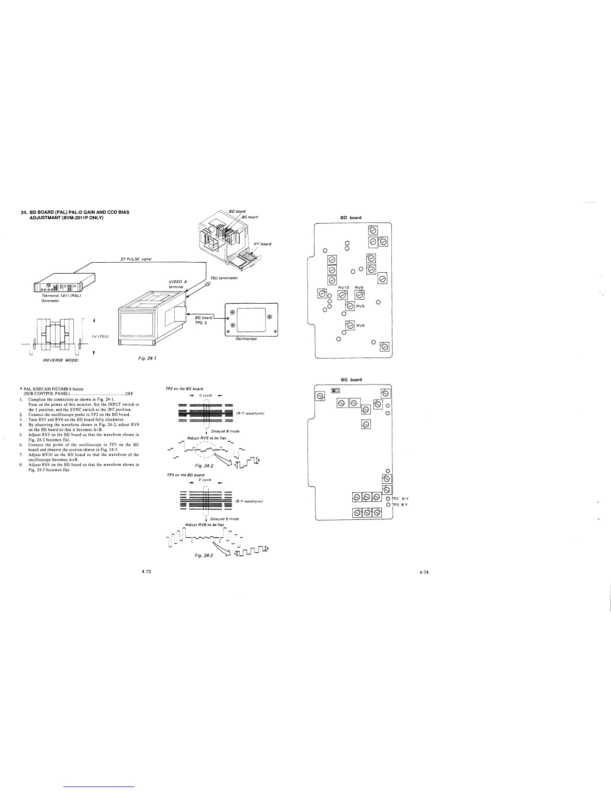
24. BD BOARD (PAL) PAL-D GAIN AND CCD BIAS
ADJUSTMANT (BVM-2011 P ONLY)
2T PULSE signal
Tektronix 1411 (PAL)
Generator
(REVERSE MODE)
Fig. 24-1
• PAL S/SECAM F/COMB S button
(SUB CONTPOL PANEL) .................................................. OFF
1. Complete the connection as shown in Fig. 24-1.
Turn on the power of this monitor. Set the INPUT switch to
the 1 position, and the SYNC switch to the INT position.
2. Connect the oscilloscope probe to TP2 on the BG hoard.
3. Turn RVS and RV6 on the BD board fully clockwise.
4. By observing the waveform shown in Fig. 24-2, adjust RV9
on the BD hoard so that it becomes A=B.
5. Adjust RVS on the BD hoard so that the waveform shown in
Fig. 24-2 becomes flat.
6. Connect the probe of the oscilloscope to TP3 on the BG
board and observe the section shwon in Fig. 24-3.
7. Adjust RVlO on the BD hoard so that the waveform of the
oscilloscope becomes A=B.
8. Adjust RV6 on the BD hoard so that the waveform shown in
Fig. 24-3 becomes flat.
4-73
15rt terminator
VIDEO A
BG board '---+-00• @ D @
TP2,3 @
@) @)
Oscilloscope
TP2 on the BG board
-- V cycle ..J
==
• - (Hwm(orm(
',,__)
+ Delayed 8 mode
Adjust RV5 to be flat.
Ji
~~
I / '
~( r-""'1-~ ...... :
~
/~ : ;'""-
Fi:.~~-2
~~
TP3 on the BG board
V cycle
=
(8-Y waveform)
l Delayed 8 mode
Adjust R V6 to be flat.
r, r
,-, ! I , '"'
IL, i ! ': r--,
,r
I I I
uw
w ~(u•· -
~
'"'_:,..,nm
Fig. 24-3
~
AILJ LJ L.....l _B
BD board
~
0
~~
0
0
[Q]
[Q]
[Q]
00
~
[Q]
[Q]
RV1O RV9
[Q)o [@ [Qj
g r01RV5
0
0 0
fblRV6
0
0
0~
BG board
~
[Q][QJ[@l[Q]~
~
R-Y
B-Y
4-74