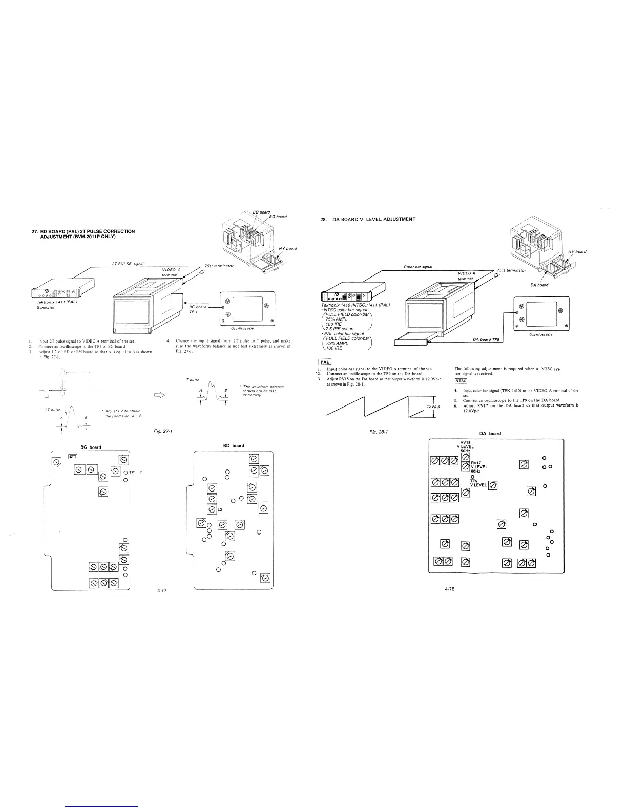
27. BO BOARD (PAL) 2T PULSE CORRECTION
ADJUSTMENT (BVM-2011 P ONLY)
Tektronix 1411 (PAL)
Generator
2T PULSE signal
0
l. Input 2T pulse signal to VlDEO A terminal of the set.
2. Connect an oscilloscope to the TPl of BG board.
3. Adjust L2 of BD or BM board so that A is equal to Bas shown
in Fig. 2 7-1.
2T pulse (\
' . .
• Ad;ust L2 to obtain
the cond1 t1on A " 8 .
A !
8
BG board
fQ]
~~~~
~rn v
~
o®D®
@
@) @)
Oscilloscope
4. Change the input signal from 2T pulse to T pulse, and make
sure the waveform balance is not lost extremely as shown in
Fig. 27-1.
T pulse
/~
A / ·, 8
' I \\J~~
y t
• The waveform balance
should not be lost
ex tremelv.
Fig. 27-1
BD board
~
0
~[Q]
0
0
,..,
~
~
~
oO
~
[Q]L2
[Q]
[Q)o [Q) [Q)
0
0
00
~
0
~
0
0
0 [Q]
4-77
28. DA BOARD V. LEVEL ADJUSTMENT
I.
'2.
3.
Tektronix 1410 (NTSC)/1411 (PAL)
• NTSC color bar signal
(
FULL FIELD color-ba)
75%AMPL
100 IRE
7.5 IRE set up
• PAL color bar signal
(
FULL FIELD color-ba)
75%AMPL
100 IRE
Color-bar signal
75n terminator
~
DA board
®D®
@)
@ @
Oscilloscope
DA board TP9
Input color-bar signal to the VIDEO A terminal of the set.
Connect an oscilloscope to the TP9 on the DA board.
The following adjustment is required when a NTSC sys-
tem signal is received.
Adjust RVl8 on the DA board so that output waveform is 12.0Vp-p
as shown in Fig. 2 8-1.
JNTSC/
Fig. 28-1
4. Input color-bar signal (TEK-1410) to the VIDEO A terminal of the
set.
5. Connect an oscilloscope to the TP9 on the DA board.
12Vp-p
+
6. Adjust RVl 7 on the DA board so that output waveform is
12.0Vp-p.
DA board
RV18
V LEVEL
50Hz
101~ 11RV17
0
~
/ V LEVEL
oo
60Hz
0
~~~
~~
9
EVEL~
~
0
~~~[@
~~~
~
~
0
0
~
~
0
[@
~
0
0
~~
0
~
~
ffl
4-78