rf)
f-
z
UJ
::;
f-
rf)
::,
3
..:
._;
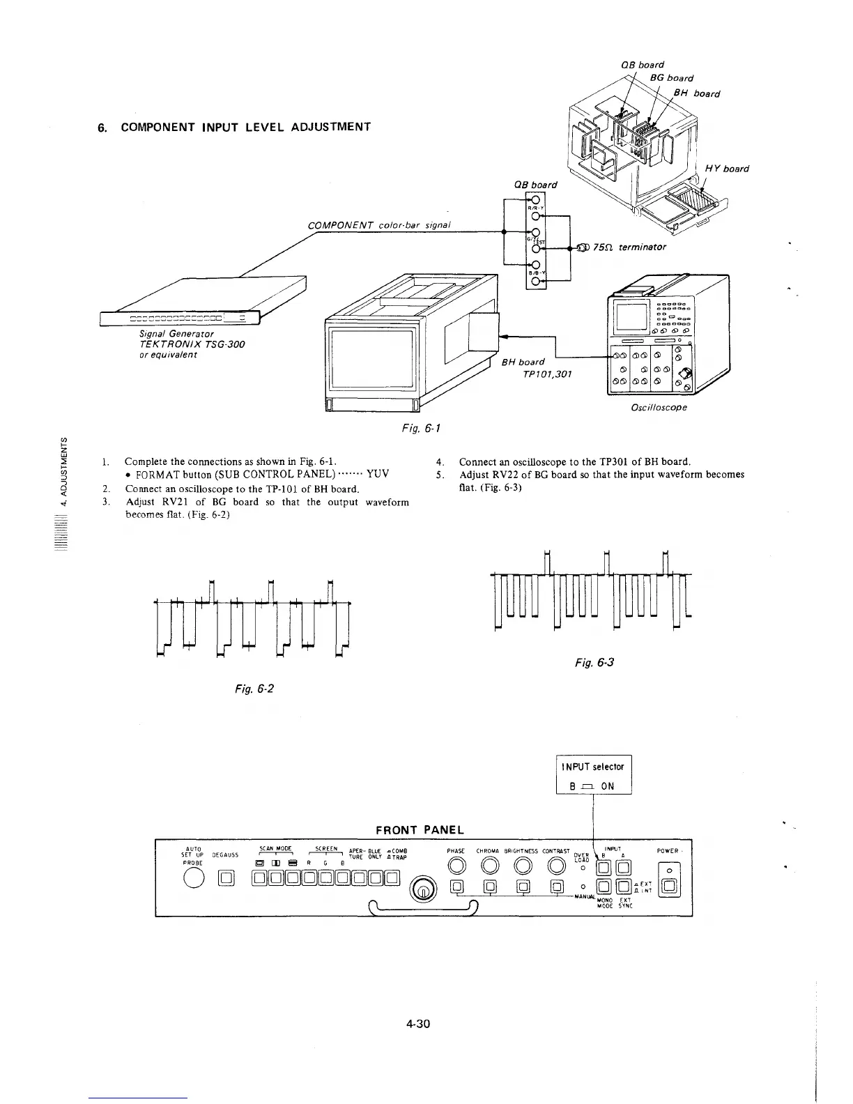
6. COMPONENT INPUT LEVEL ADJUSTMENT
COMPONENT color-bar signal
Signal Generator
TEKTRONIX TSG-300
or equivalent
Fig. 6-1
QB board
= =o
~----t!"-"6l 6) 6) 6)
BH board
TP/01,301
6) 6)
6)6) 6) 6)
Oscilloscope
l. Complete the connections as shown in Fig. 6-1.
4. Connect an oscilloscope to the TP301 of BH board.
• FORMAT button (SUB CONTROL PANEL) ....... YUV
2. Connect an oscilloscope to the TP-101 of BH board .
3. Adjust RV21 of BG board so that the output waveform
becomes flat. (Fig. 6-2)
Fig. 6-2
5. Adjust RV22 of BG board so that the input waveform becomes
flat. (Fig. 6-3)
~
~ ~
..
..
.. .. ..
.. .. ..
..
~
~
~
Fig. 6-3
11 NPUT selector
B .=. ON
FRONT PANEL
AUTO
~
SCREEN
APER- BLUE .a C 0MB PHASE
CHROMA BRIGHTNESS CONTRAST OV1i_R BINPUT A
POWER
SET UP DEGAUSS
r--,--i
TURE ONLY .a TRAP
PROBE
~
[I)
~
R G B
0
0 0 0 LOOO [g]g
~
0
g
ggg[g[g[g[gg[g
~
@ @ @ [g]
0 g [g;;;~;
f")
MANlW_MONO EXT
0
MODE SYN(
4-30