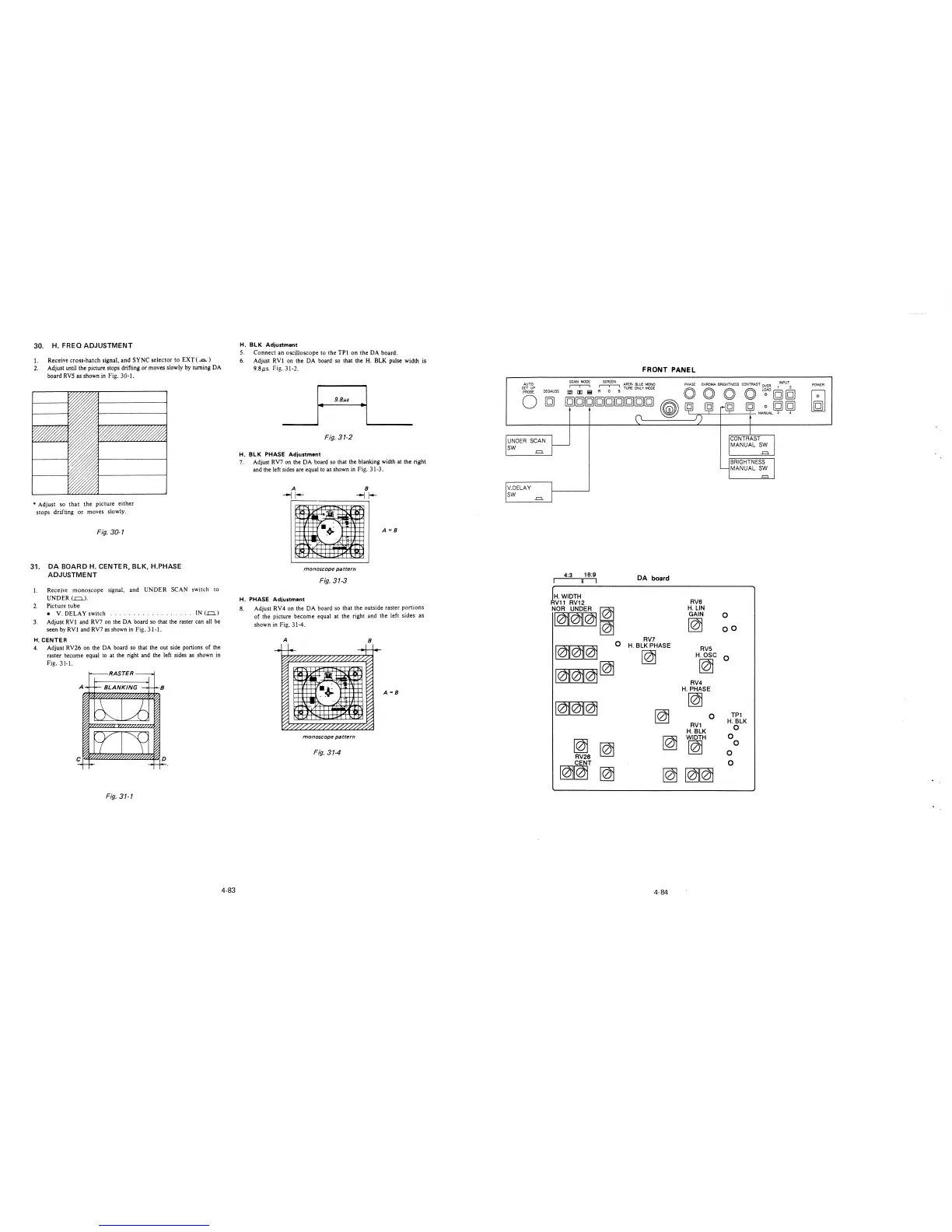
30. H. FREQ ADJUSTMENT
1. Receive cross-hatch signal, and SYNC selector to EXT ( ...c..)
2. Adjust until the picture stops drifting or moves slowly by turning DA
board RVS as shown in Fig. 30-1.
* Adjust so that the picture either
stops drifting or moves slowly.
Fig. 30-1
31. DA BOARD H. CENTER, BLK, H.PHASE
ADJUSTMENT
I.
2.
3.
Receive monoscope signal, and UNDER SCAN switch to
UNDER(.=.).
Picture tube
• V. DELAY switch
... IN (..o..)
Adjust RVl and RV7 on the DA board so that the raster can all be
seen by RV! and RV7 as shown in Fig. 31-1.
H. CENTER
4. Adjust RV26 on the DA board so that the out side portions of the
raster become equal to at the right and the left sides as shown in
Fig. 31-1.
RASTER
Fig. 31-1
4-83
H. BLK Adjustment
5. Connect an oscilloscope to the TPI on the DA board.
6. Adjust RV! on the DA board so that the H. BLK pulse width is
9.Bµs. Fig. 31-2.
-~ - ··~ ·I ____
Fig. 31-2
H. BLK PHASE Adjustment
7. Adjust RV7 on the DA board so that the blanking width at the right
and the left sides are equal to as shown in Fig. 31-3.
A
--j 1--
~
~
~ I
';iii
·""'
•.+
'
~
,-
,-
A =B
71-,..
-~
..-1
"v
I I I
...
monoscope pattern
Fig. 31-3
H. PHASE Adjustment
8. Adjust RV4 on the DA board so that the outside raster portions
of the picture become equal at the right and the left sides as
shown in Fig. 31-4.
A
8
f
iu
-~
....,,
~~
._;·
,-
,-
,-
A=B
71-_
A's
~v
II,
"loo. I
I
monoscope pattern
Fig. 314
FRONT PANEL
SCAN MODE SCREEN APER· BLUE lv'ONO
PHASE CHROMA BRIGHTNESS CONTRAST OVER l !NPU\
AUTO
SET UP
PROBE
DEGAUSS
r-r-, Rr-r-,G B TUAE ONL '( MODE
[QJ [I] !!;I
co co co co L~AD [g] [g]
0
UNDER SCAN
SW
-=
V.DELAY
SW
-=
[g][g][g][g][g][g][g][g][g]
~
4:3 16:9
11---i
H. WIDTH
Vl 1 RV12
N~,
~~~
~
~
RV26
CENT
DA board
RV7
H. BLK PHASE
~
~
~
0 [g] [g]
-~--;-----,- l'v\ANUAL 3 4
CONTRAST
MANUAL SW
.=.
BRIGHTNESS
MANUAL SW
.=.
RVS
H. LIN
GAIN
0
~
oo
RVS
H. OSC
0
~
RV4
H.PHASE
~
0
TP1
RV1
H.BLK
H.BLK
0
WIDTH
0
~
0
0
0
~~
~
~~~
4-84
POWER