AUTO
SET UP
PROBE
0
DEGAUSS
!
UNDER SCAN
SW -=.
FRONT PANEL
SCAN MODE SCREEN APER· BLUE MONO PHASE CHROMA BRIGHTNESS CONTRAST OVER
1
INPUT
2
~
~
TURE ONLY ~DE O O O O L~AD lQ) lQ)
ggggggggg
~
ml ml ml lQ) lQ)
~
~
¥ ¥ ¥MA~UAL3 4
0'-----~f)
POWER
DA board
4:3 16:9
111
~~~~
0
~
oo
V.HEIGHT
~
RV23 RV24
NOR t&i~ 0
l~/ /
~
~
0
RV19
~~~~SIDE PIN
/ / TILT
SIDE PIN
V15 RV16
~
N~~~
~
0
RV21
0
V.CENT
~
0
RV25~
~RV20
~
0
V. LIN
0
H.CENT
BALANCE
LIN
0
~~
~RV22
~~~
V. LIN
GAIN
4-81
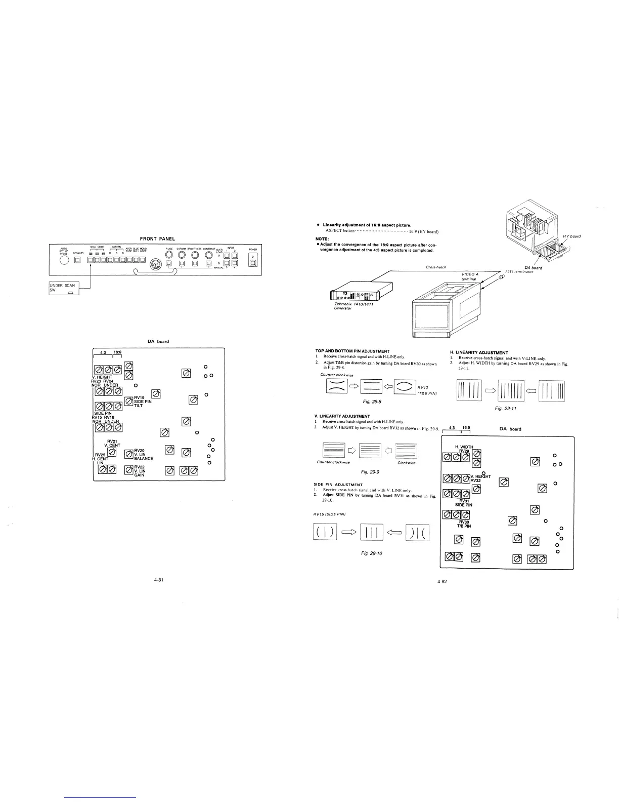
• Linearity adjustment of 16:9 aspect picture.
ASPECT button· .... · .............................. 16:9 (HY board)
NOTE:
• Adjust the convergence of the 16:9 aspect picture after con-
vergence adjustment of the 4:3 aspect picture is completed.
Tektronix 1410/1411
Generator
TOP AND BOTTOM PIN ADJUSTMENT
I. Receive cross-hatch signal and with H-LINE only.
Cross-hatch
DA board
75n terminator
H. LINEARITY ADJUSTMENT
I. Receive cross-hatch signal and with V-LINE only.
2. Adjust T&B pin distortion gain by turning DA board RV30 as shown
in Fig. 29-8.
2. Adjust H. WIDTH by turning DA board RV29 as shown in Fig.
29-11.
Counter clockwise
Fig. 29-8
Fig. 29-11
V. LINEARITY ADJUSTMENT
I. Receive cross-hatch signal and with H-LINE only.
4:3 16:9
2. Adjust V. HEIGHT by turning DA board RV32 as shown in Fig. 29-9. r----,r--,
DA board
[3o~oi~
H. WIDTH
RV~;
0
~01(2)1
~
Counter-clockwise
Clockwise
oo
Fig. 29-9
~~V. HElcaHT
RV32
~
0
SIDE PIN
ADJUSTMENT
~~
~
I.
Receive cross-hatch si~nal and with V. LINE only.
2.
Adjust SIDE PIN by turning DA board RVJI
as shown in Fig.
29-10.
RV31
SIDE PIN
~
le)j@Q)j
RV15 (SIDE PIN/
~
RV30
0
[TI]
~
[ill] ¢= ITIT]
T/BPIN
0
~
0
~
~
~
0
0
0
Fig. 29-10
~
~
~
~~
4-82