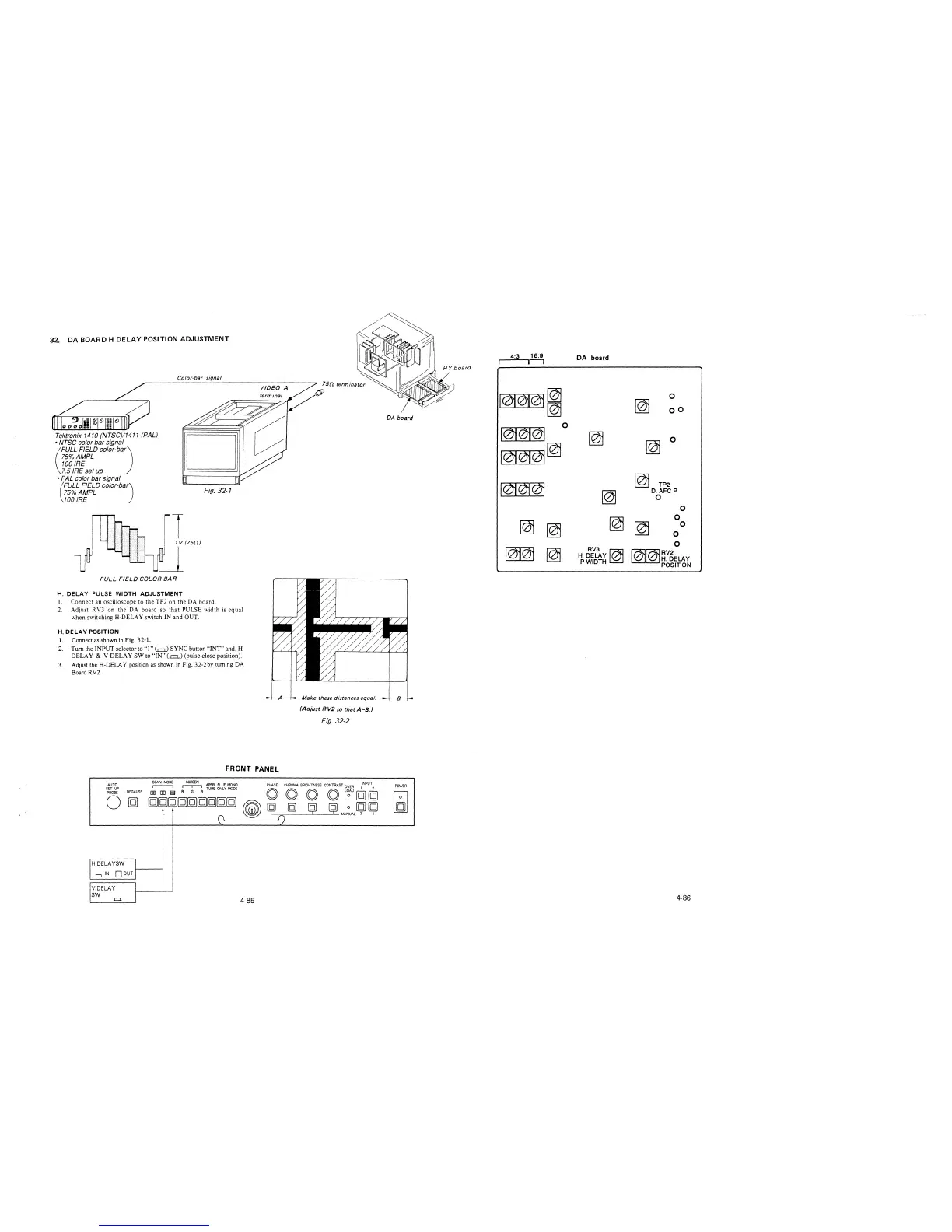
32. DA BOARD H DELAY POSITION ADJUSTMENT
Tektronix 1410 (NTSC)/1411 (PAL)
• NTSC color bar signal
(
FULL FIELD color-bar)
75%AMPL
100 IRE
7.5 IRE set up
• PAL color bar signal
Color-bar signal
75% AMPL Fig. 32-1
(
FULL FIELD color-bar)
100 IRE
FULL FIELD COLOR-BAR
H. DELAY PULSE WIDTH ADJUSTMENT
l. Connect an oscilloscope to the TP2 on the DA board.
2. Adjust RV3 on the DA board so that PULSE width is equal
when switching H-DELA Y switch IN and OUT.
H. DELAY POSITION
1. Connect as shown in Fig. 32-1.
2. Turn the INPUT selector to "I"(=) SYNC button "INT" and, H
DELAY & V DELAY SW to "IN"(.=.) (pulse close position).
3. Adjust the H-DELA Y position as shown in Fig. 32-2 by turning DA
Board RV2.
A
FRONT PANEL
Make these distances equal.
(Adjust RV2 so that A=B.)
Fig. 32-2
AUTO
~
~
APER-BLUE MONO PHASE CHROMA BRIGHTNESS CONTRAST OVER INPUT
SET UP
[§] [E i;! R G B TUREONLYMODE O O O O L~ [g] [g]
PROBE
DEGAUSS
0
[g]
[g][g][g][g][g][g][g][g)[g]
~
~
ij (91 [@ 0 [g] [g]
0
1) MANUAL 3 4
H.DELAYSW
I
,=.IN nourj
V.DELAY
I
SW
I
.=.
4-85
4:3
16:9
DA board
lr-1
~1
0
co
DA board
~
0
~
~
0
~~
~
~
TP2
~
D.AFC P
0
0
~
~
~
0
~
0
0
0
m
~
RV3
~
~~RV2
H. DELAY
/ H. DELAY
PWIDTH
POSITION
B
POWER
~
4-86