BC board
BG board
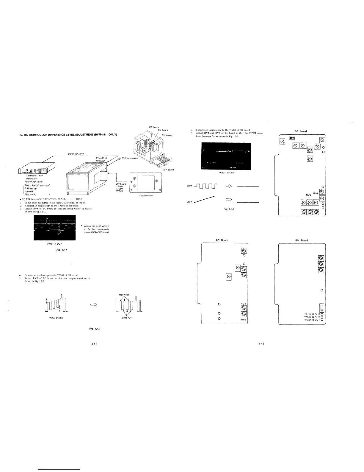
12. BC Board COLOR DIFFERENCE LEVEL ADJUSTMENT (BVM-1911 ONLY)
Tektronix 1410
Generator
*Color-bar signal
(
FULL FIELD color-bar)
1.5% set up
100 IRE
75% AMPL
Color-bar signal
• YC SEP button (SUB CONTROL PANEL)········· TRAP
1. Input color-bar signal to the VIDEO A terminal of the set.
2. Connect an oscilloscope to the TPl0l of BH board.
3. Adjust RV4 of BC board so that the levels with + is flat as
showninFig.12-1.
* Adjust the levels with ·:·
to be flat respectively
useing RV4 of BC board.
TP101 ROUT
Fig. 12-1
4. Connect an oscilloscope to the TP301 of BH board.
5. Adjust RVS of BC board so that the output waveform as
shown in Fig. 12-2.
TP301 BOUT
Fig. 12-2
4-41
6' 151:/. terminator
BH board
TP101
TP201
TP301
·®D®
@
® ®
Oscilloscope
Make flat
HY board
6. Connect an oscilloscope to the TP201 of BH board.
7. Adjust RV4 and RVS of BG board so that the INPUT wave-
form becomes flat as shown in Fig. 12-3.
TP201 GOUT
RV4~
RV5~
Fig. 12-3
BC Board
0
0
0
~
~
0
0
~~
~
RV4
~
~
RV5
4-42
BG board
[g
~
~~~~~
~
BH Board
~
~
~
0
~
TP101 R OUTQ
TP201 G OUT8
TP301 BOUT