0 GN/TEST INPUT connectors (BNC)
0 R/R-Y INPUT connectors (BNC)
0 B/B-Y INPUT connectors (BNC)
Input RGB video signals, component signals or a
composite test signal. The signal format can be
selected with the FORMAT button in the drawer.
Use one connector of each pair for input and the
other for loop-through output.
When the loop-through output is not used, attach a
75-ohm terminator.
f) DECODER OUTPUT connectors (BNC)
Output RGB or component (Y, R-Y, B-Y) outputs
decoded from the composite (VIDEO A, VIDEO B
or TEST) or component signals being displayed on
the screen with the BKM-1440 RGB/component
adaptor installed.
The RGB or component outputs are selected with
the SI selector on the BF board of the BKM-1440
kit.
To provide RGB output, set the SI selector to the
upper position.
To provide component output, set it to the lower
position.
•@ta
• The DECODER OUTPUT connectors do not
provide the correct RGB outputs when RGB
signals are displayed on the screen. To obtain
the correct RGB outputs, use the loop-through
outputs of the R, G and B INPUT connectors.
• The outputs obtained from noncomposite signals
are also noncomposite. Supply a sync signal
from the EXT SYNC INPUT connector when
required.
• The output signals are affected by the
CHROMA, PHASE and APERTURE controls
and MATRIX switch.
• The color killer circuit is not activated for output
signals.
(l) REMOTE connector
Connect to an external control device using the
supplied I 0-pin connecter.
To enter remote control mode, press the LOCAL/
REMOTE button in the drawer so that the
associated lamp lights.
The input mode and the pin assignment can be set
through the REMOTE menu operation.
See "1-4-6. Assigning the Remote Control Functions."
0 Ground terminal
Connect to the system ground, when required.
~
Voltage selector
Set to 100-120V ACfortheBVM-1911 or220-
240 V AC for the BVM-201 IP.
~
Fuse
Use a 4A fuse for the BVM-1911 or a T2A fuse
for the BVM-201 IP.
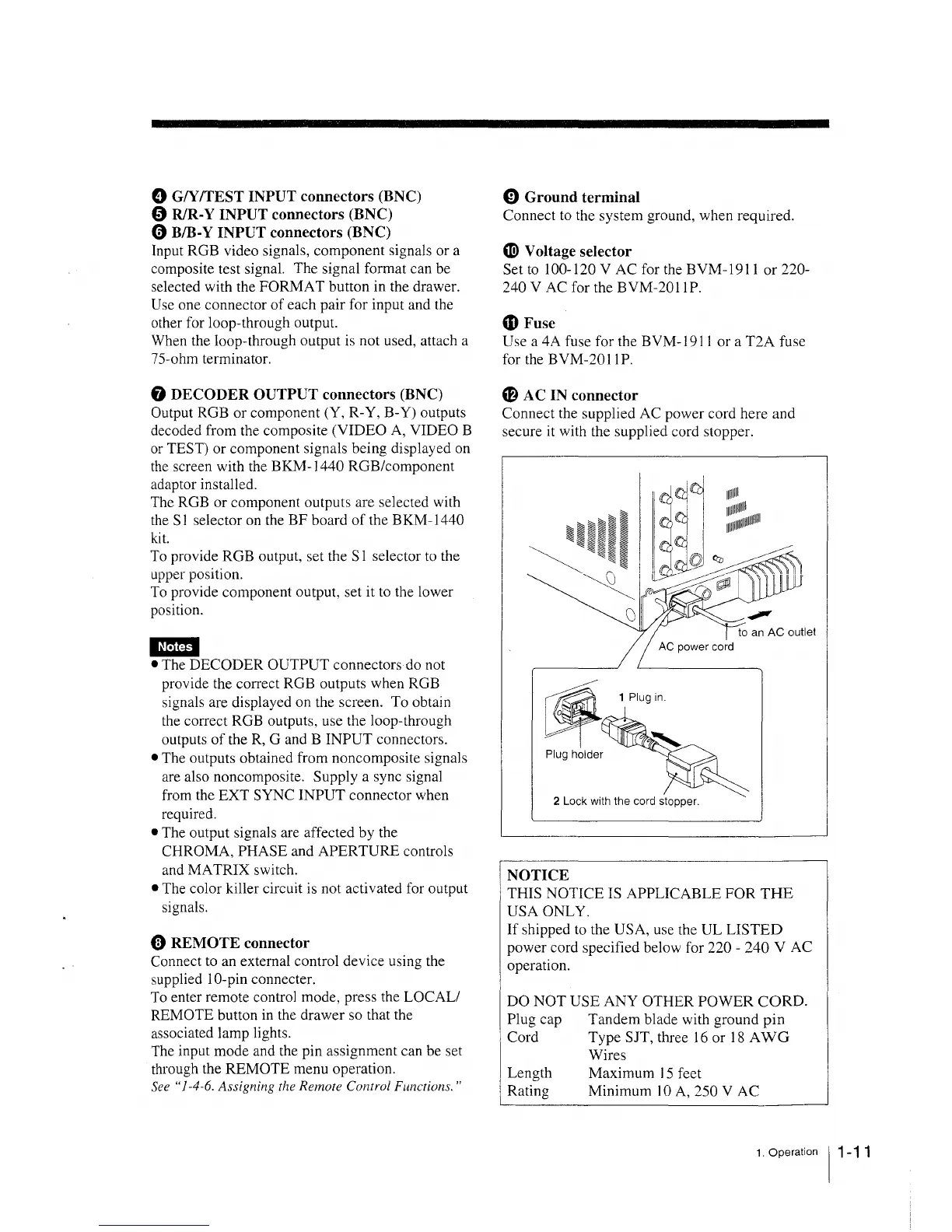
Cf} AC IN connector
Connect the supplied AC power cord here and
secure it with the supplied cord stopper.
11111111
1111111111111
1111111111111111111111
2 Lock with the cord stopper.
NOTICE
THIS NOTICE IS APPLICABLE FOR THE
USA ONLY.
If shipped to the USA, use the UL LISTED
power cord specified below for 220 - 240 V AC
operation.
DO NOT USE ANY OTHER POWER CORD.
Plug cap
Cord
Length
Rating
Tandem blade with ground pin
Type SJT, three 16 or 18 A WG
Wires
Maximum 15 feet
Minimum IO A, 250 V AC
1. Operation 11 -11